Capacitor having adjustable capacitance, and printed wiring board having the same

Active Publication Date: 2008-01-31
IBIDEN CO LTD
View PDF2 Cites 7 Cited by
  • Summary
  • Abstract
  • Description
  • Claims
  • Application Information

AI Technical Summary

Benefits of technology

[0024]The present invention can provide a novel capacitor having an adjustable capacitance, and a method of fabricating the capacitor.
[0025]In addition, the present invention can provide a novel printed wiring board including a capacitor having an adjustable capacitance, and a method of fabricating the printed wiring board.

Problems solved by technology

However, the present inventors found that the above-mentioned conventional methods of adjusting the capacitance have various problems caused by laser irradiation.

Method used


Image

  • Capacitor having adjustable capacitance, and printed wiring board having the same
  • Capacitor having adjustable capacitance, and printed wiring board having the same
  • Capacitor having adjustable capacitance, and printed wiring board having the same

Examples


first embodiment

(Outlines)

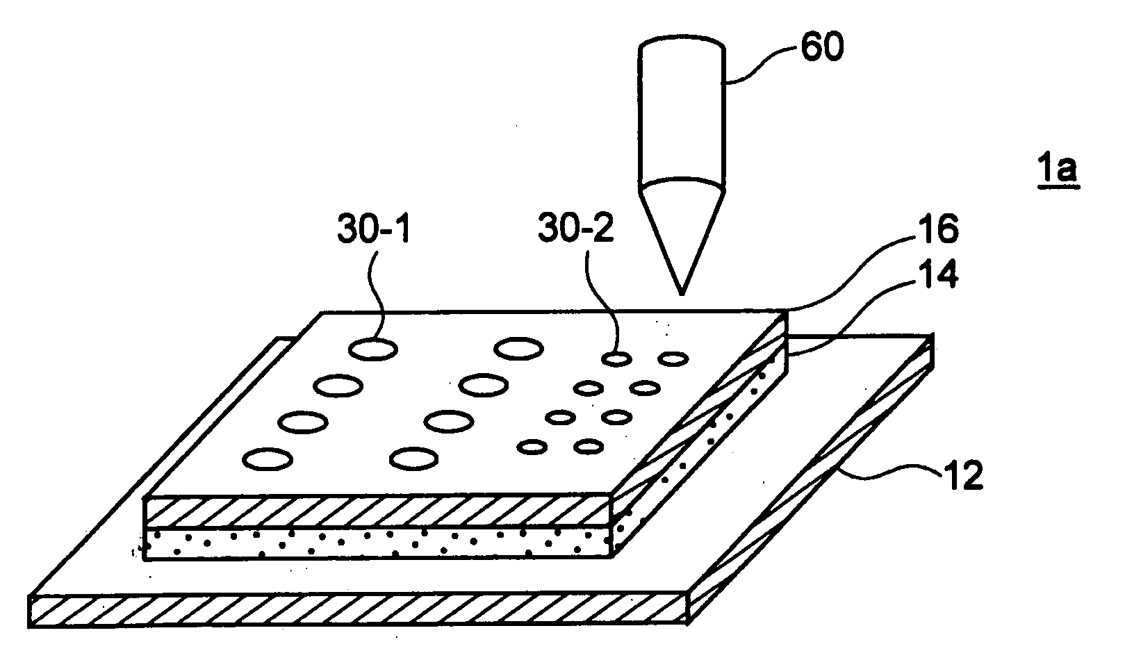
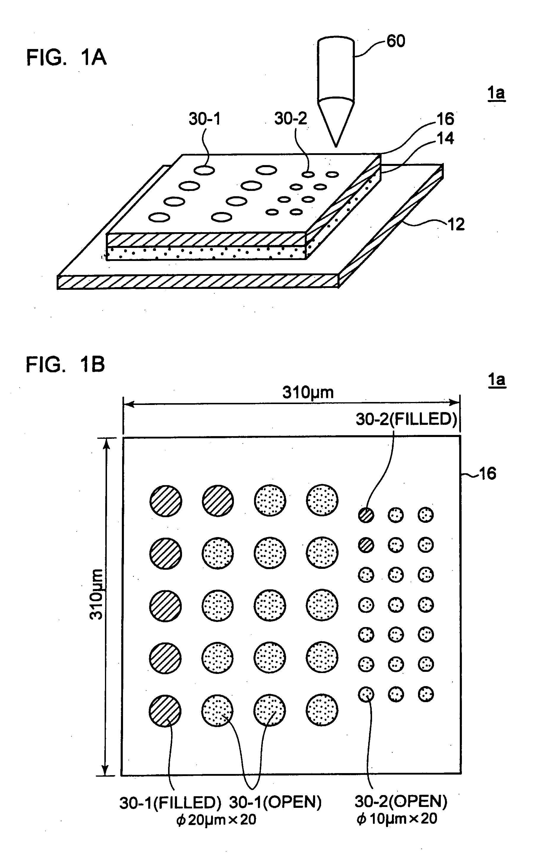
[0036]FIG. 1A shows a capacitor having an adjustable capacitance according to a first embodiment of the present invention.

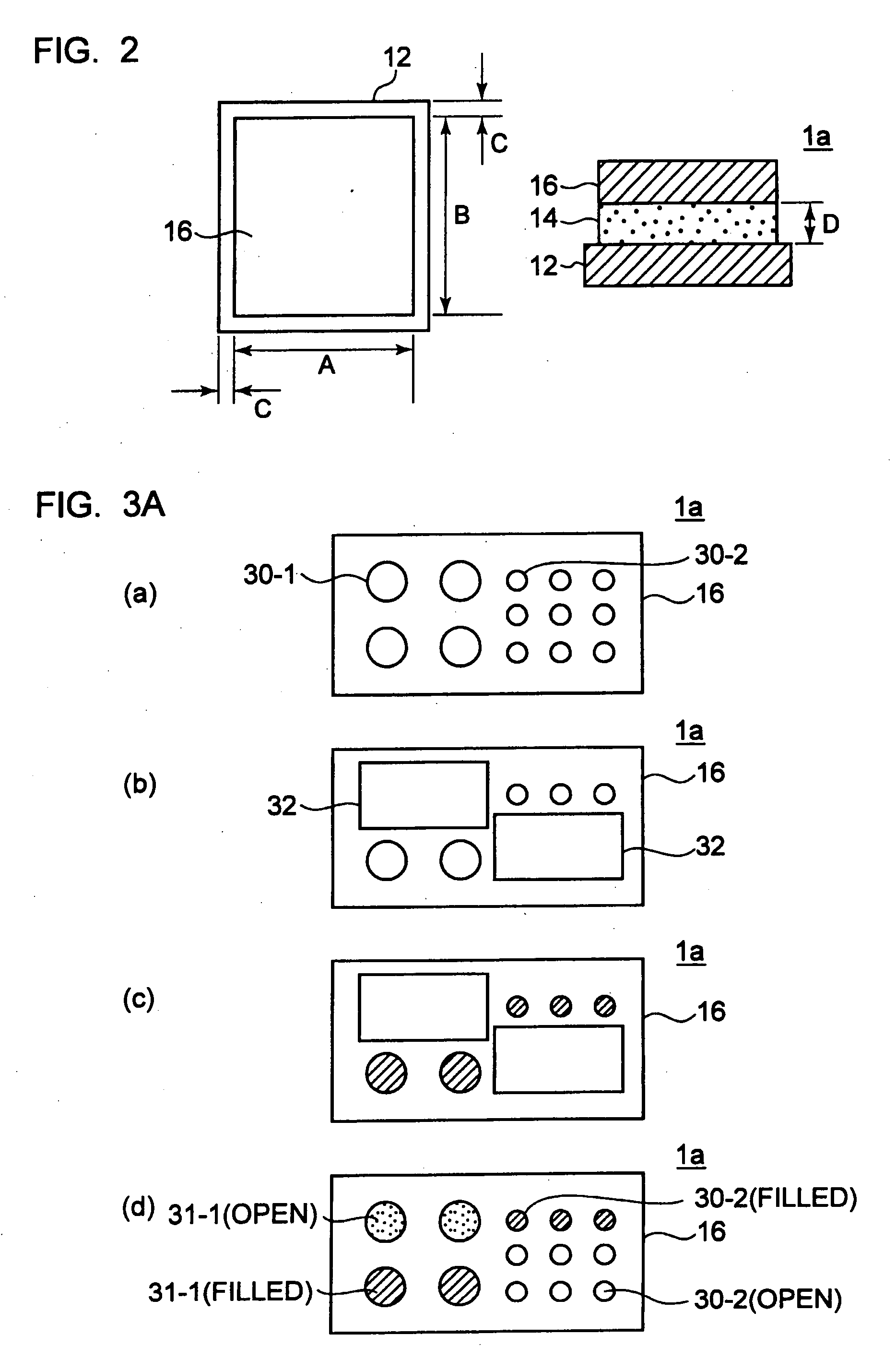
[0037]The capacitor 1a according to the first embodiment has an upper electrode 16 on which predetermined numbers of openings 30-1 and 30-2 having predetermined diameters are formed. The capacitance of the capacitor 1a is adjusted by filling a necessary number of the openings with an electroconductive material.

[0038]The capacitor 1a according to the first embodiment comprises the upper electrode 16, a lower electrode 12, and a dielectric layer 14 arranged between the two electrodes. The two electrodes 16 and 12 each comprise a metal layer. They preferably comprise, for example, a copper (Cu) layer. Materials for the dielectric layer 14 are commercially available typically as high-dielectric laminates and high-dielectric films. Examples thereof are the products of Matsushita Electric Works, Ltd. (Japan) under the model name of “High-Dk Capacitor Film”, t...

second embodiment

(Outlines)

[0066]FIG. 4 shows a capacitor 1b having an adjustable capacitance according to a second embodiment. The capacitor 1b comprises an upper electrode 16, a lower electrode 12, and a dielectric layer 14 arranged between the pair of electrodes. The electrodes 16 and 12, and the dielectric layer 14 are same as with those in the capacitor 1a according to the first embodiment.

(Method of Adjusting Capacitance)

[0067]According to the capacitor 1b of the second embodiment, the upper electrode 16 is formed to have an apparent electrode area smaller than the area of the lower electrode 12. The upper electrode 16 has an apparent area Sb and an effective area Seff equal to each other because of no opening. The capacitance of the capacitor 1b in this state is measured. Next, an electroconductive material such as a copper (Cu) paste or a silver (Ag) paste is ejected as a discharged electroconductive material 16-1 to an adjacent region of the upper electrode 16 using a discharger 62 to there...


PUM


Abstract

The capacitance of a capacitor is adjusted by forming openings in one of a pair of electrodes of the capacitor, the openings having different sizes d1, d2, d3, wherein d1>d2>d3> . . . and being arranged in numbers n1, n2, n3, . . . , respectively; and sequentially filling a necessary number of the openings with an electroconductive material in descending order of the size so as to adjust the capacitance gradually with an increasing degree of precision. The resulting capacitor is mounted to a printed wiring board.

Description

BACKGROUND OF THE INVENTION[0001]1. Field of the Invention[0002]The present invention relates to capacitors having adjustable capacitance, and printed wiring boards having the capacitors.[0003]2. Description of the Related Art[0004]Printed wiring boards are originally used for mechanically holding electronic components such as semiconductor devices, for feeding these electronic components, and for establishing electric interconnections between the electronic components. The printed wiring boards therefore comprise, for example, land, pad, and through-hole conductors for mechanically holding the electronic components; wiring pattern conductors, via-hole conductors, and through-hole conductors for feeding them and establishing electric interconnection of them; and dielectric layers for mechanically holding these land, pad, and through-hole conductors, via-hole conductors, and wiring pattern conductors.[0005]Printed wiring boards embedded resistor, inductor and / or capacitor components ...

Claims


Application Information

Patent Timeline
Patent Type & Authority Applications(United States)
IPC IPC(8): H01G4/005
CPCH01G2/06H01G4/005H05K1/162H05K2203/171H05K2201/09509H05K2201/0969H05K3/4644
Inventor SAKAMOTO, HAJIMEKARIYA, TAKASHIMANO, YASUHIKO
Owner IBIDEN CO LTD
Why Eureka
Try Eureka