Cervical Intervertebral Disc Prosthesis Comprising An Anti-Dislocation Device And Instruments

a technology of cervical disc and anti-dislocation device, which is applied in the field of cervical intervertebral disc prosthesis, can solve the problems of screw and flange dimensions that need to be enlarged, difficult to reconcile, and affect the risk of spinal nerve damage, and achieves good force transmission, great strength, and no risk of bone splintering

Inactive Publication Date: 2008-01-31
CERVITECH INC
View PDF4 Cites 256 Cited by
  • Summary
  • Abstract
  • Description
  • Claims
  • Application Information

AI Technical Summary

Benefits of technology

[0012] An instrument according to the invention for implanting a cervical intervertebral prosthesis of the type mentioned at the outset comprises a handle, a stem, and a head part which is arranged at an end remote from the handle and whose dimensions are chosen such that it can be inserted into the space that has been created for receiving the intervertebral prosthesis, the head part having an excavating element for creating a recess in the cranial-caudal direction, and an actuating device is provided for the excavating element which is movable between a rest position, in which it is retracted in the head part, and a working position, in which it protrudes from the head part transversely with respect to the stem. The instrument can be pushed with its head part toward the intended implantation site, which has been prepared in a manner known per se. When the excavating element is located in its rest position, in which it is retracted in the head part, said head part can be advanced to the intended implantation site without any difficulty. X-ray checks are expediently carried out to verify that the correct position has been reached. For this purpose, it may be expedient to provide separate X-ray markings on the head part. To create a recess on the end face of the vertebral body into which a rib-like projection arranged on the anchoring plate of the intervertebral prosthesis can engage with a form fit, the excavating element is moved into its working position. The recess can then be created by actuating the excavating element. In order to withdraw the instrument, the excavating element can then be returned to its retracted rest position. The excavating element can be driven out on one side or on both sides. The invention thus makes available an instrument, used for implanting the intervertebral prosthesis according to the invention, which can be easily advanced to the intended implantation site and which, in this position, creates recesses allowing the projections to engage with a form fit in the vertebral body.
[0025] The projection can have a height of 0.3 to 0.5 mm, preferably 1.0 to 3.0 mm, above the level of the anchoring plate surface. If the latter is provided with teeth, which is of advantage for further increasing the reliability of the connection, the level of the anchoring plate surface is then defined by the top edge of the teeth. The projection is advantageously designed narrowing toward the top. This permits a self-centering effect during insertion of the anchoring plate on the vertebral body. Small inaccuracies can be compensated in this way. Implantation is made easier.

Problems solved by technology

Even a very slight displacement of prosthesis parts in the dorsal direction entails a risk of affecting the spinal nerves.
However, in the region of the cervical spine in particular, this is difficult because the small dimensions mean there is little space available.
To obtain a sufficiently secure connection, the screws and the flange need to have dimensions which are difficult to reconcile with the difficult implantation conditions in the region of the spinal column.
This does not permit any securing against undesired movement in the AP direction.
This increases the risk of incorrect positioning.
Difficulties arise, however, in forming suitable depressions in the vertebral body for receiving the pins.
This cannot successfully be done with the required precision, so that the prosthesis often has some play.
Because of its rounded shape, a sufficient locking action cannot be obtained with this.

Method used


Image

  • Cervical Intervertebral Disc Prosthesis Comprising An Anti-Dislocation Device And Instruments
  • Cervical Intervertebral Disc Prosthesis Comprising An Anti-Dislocation Device And Instruments
  • Cervical Intervertebral Disc Prosthesis Comprising An Anti-Dislocation Device And Instruments

Examples


Embodiment Construction

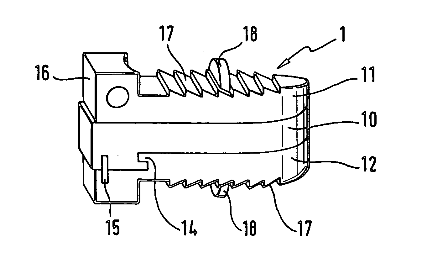
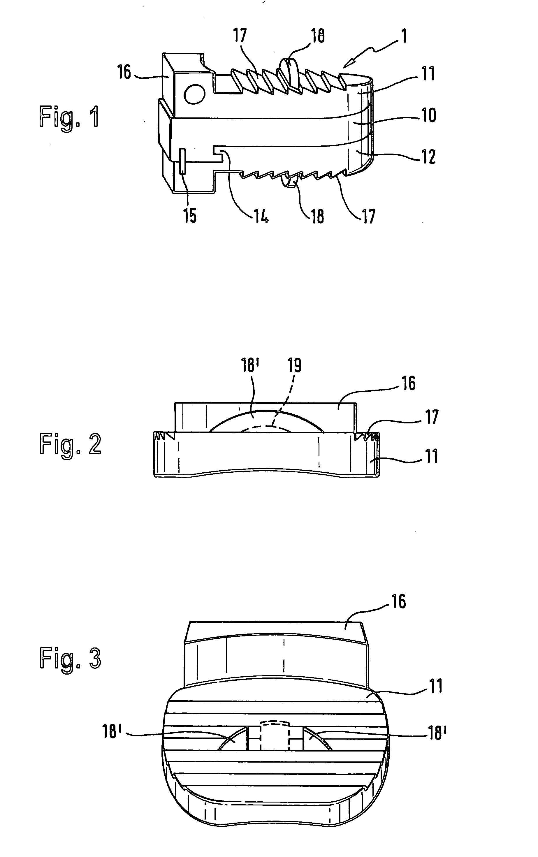
[0040] The illustrative embodiment shown in FIGS. 1 to 3 involves a cervical prosthesis according to the invention which is designated overall by reference number 1. It is provided for implantation in the space between two adjacent vertebral bodies of the cervical spine (see FIG. 13).

[0041] The cervical prosthesis 1 comprises an upper closure plate 11 and a lower closure plate 12, with a sliding core 10 arranged between them. The cervical prosthesis 1 is provided for implantation in the space between two adjacent vertebrae of the cervical spine of a human. The upper anchoring plate 11 is secured to the bottom face of the cranial vertebra, and the lower anchoring plate 12 is secured to the top face of the caudal vertebra. The anchoring plates 11, 12 are made of a hard, resistant material, in particular titanium, or another biocompatible material. At least those surfaces of the anchoring plates 11, 12 serving to bear on the adjacent vertebral bodies are preferably provided with a coa...


PUM

PropertyMeasurementUnit
heightaaaaaaaaaa
heightaaaaaaaaaa
diameteraaaaaaaaaa

Abstract

A cervical intervertebral prosthesis includes lower and upper anchoring plates with a prosthesis core arranged between them to create an articulated connection. The anchoring plates are designed to bear with their anchoring plate surfaces on adjacent vertebral bodies. At least one anchoring plate surface has a rib-like projection thereon which can be used to engage in the vertebral body with a form fit. In order to produce a corresponding recess in the vertebral body, an instrument having a handle, a stem, a head part and an excavating element that can be retracted into the head part may be used. This permits considerably improved securing of the cervical intervertebral prosthesis against unintended movement. The medullary canal running along the posterior margin of the vertebral column is in this way protected from damage.

Description

REFERENCE TO RELATED APPLICATIONS [0001] This application is a national stage application under 35 USC 371 of International Application No. PCT / EP2005 / 001956, filed Feb. 24, 2005, which claims the priority of European Application No. 04 005 341.5, filed Mar. 5, 2004, the contents of both of which prior applications are incorporated herein by reference.FIELD OF THE INVENTION [0002] The invention relates to a cervical intervertebral prosthesis comprising a lower anchoring plate and an upper anchoring plate, and a prosthesis core which is arranged between these and which creates an articulated connection between the anchoring plates, and also to an instrument for implanting such a prosthesis. BACKGROUND OF THE INVENTION [0003] Intervertebral prostheses intended for implantation in the cervical region of the spinal column have to be positioned with the utmost precision, because of the small dimensions of the spinal column in this region. After it has been implanted and anchored in the b...

Claims


Application Information

Patent Timeline
Patent Type & Authority Applications(United States)
IPC IPC(8): A61B17/56A61F2/44A61B17/16A61F2/00A61F2/30A61F2/46
CPCA61B17/1659A61F2310/00796A61F2/30767A61F2/4425A61F2/4684A61F2002/30116A61F2002/30245A61F2002/30383A61F2002/30451A61F2002/30492A61F2002/30517A61F2002/30576A61F2002/30772A61F2002/30878A61F2002/30879A61F2002/30891A61F2002/30904A61F2002/443A61F2220/0025A61F2220/0058A61F2230/0006A61F2230/0071A61F2310/00023A61B17/1671A61B17/88A61F2/44A61B17/58A61B17/70
Inventor LINK, HELMUT D.KELLER, ARNOLD
Owner CERVITECH INC
Why Eureka
Try Eureka