

Non-Contact Conveying Device Using Superconducting Magnetic Levitation
- Summary
- Abstract
- Description
- Claims
- Application Information
AI Technical Summary
Benefits of technology
Problems solved by technology
Method used
Image

Examples
examples
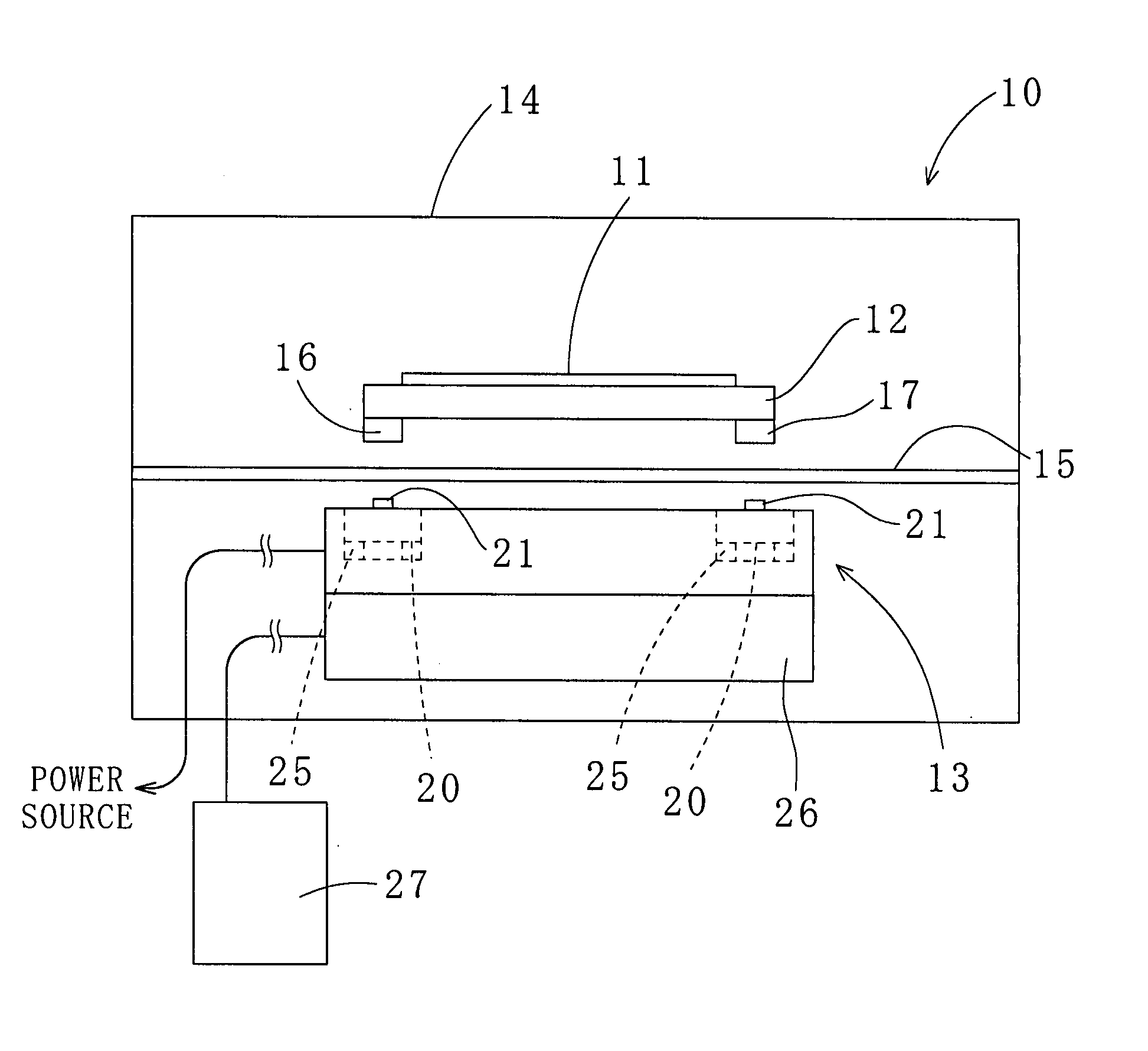
[0043] The following discusses experiments that were performed to verify functions and effects of the present invention. As illustrated in FIG. 6, a device 40 used in the experiments employs the dual partitioned superconductor 20 shown in FIG. 3. The damping coil 25 is disposed at the bottom of the superconductor 20. A Hall element 41, an example of a distance sensor, is placed on the superconductor 20 to detect vertical displacement of a disk-shaped permanent magnet 42 (i.e., a gap between the permanent magnet 42 and the superconductor 20). The permanent magnet 42 configures a simulated conveying table. FIG. 7 illustrates the relationship between an output value of the Hall element 41 and the gap. FIG. 7 shows that the output of the Hall element 41 was proportional to the gap when the permanent magnet 42 was placed in a prescribed position and the gap was varied.
[0044] Signals from the Hall element 41 are fed back to the damping coil 25 via an AD converter 43, a differentiating ci...
PUM
 Abstract
Description
Claims
Application Information