Motor rotor and method for forming the same

a technology of motor rotor and rotor body, which is applied in the direction of magnetic circuit rotating parts, dynamo-electric machines, magnetic circuit shape/form/construction, etc., can solve the problems of vibration and other unacceptable effects in certain motor applications, and achieve the effect of simplifying the design process

Inactive Publication Date: 2018-07-05
CHICONY POWER TECH CO LTD
View PDF4 Cites 0 Cited by
  • Summary
  • Abstract
  • Description
  • Claims
  • Application Information

AI Technical Summary

Benefits of technology

[0006]This disclosure provides a motor rotor and a method for forming the same to reduce the harmonic components with second order or with an order more than second order in magnetic flux density distribution in the corresponding airgap and simplify the design process.
[0019]When the motor rotor is used, the magnet generates magnetic fields in the airgap between the motor rotor and the outer stator, such that the corresponding magnetic flux density distribution is generated in the airgap. Theoretically, the magnetic flux density distribution is sinusoidal, so that the induced electromotive force is sinusoidal as well. However, in the real situation, the magnetic flux density distribution often includes first order harmonics and harmonics with second order or with an order more than second order, so that the induced electromotive force includes first order harmonics and harmonics with second order or with an order more than second order as well. When the induced electromotive force includes harmonics with second order or with an order more than second order, vibrations and other unacceptable effects in certain motor applications may happen. Since the relation is a rose curve, the shape of the airgap varies sinusoidally by making the outer contour of the cross-sections of an even number of the protrusions of the body of the motor rotor conform to at least a portion of the periphery of the curve. The experiments show that the harmonic components with second order or with an order more than second order in magnetic flux density distribution can be effectively reduced.
[0020]Further, since the outer contour of the cross-sections of an even number of the protrusions of the body of the motor rotor conforms to at least a portion of the periphery of the curve, the shape of the outer contour of the cross-sections of all of the protrusions can be obtained immediately after k, n, and d are determined. Therefore, during the design process of the shape of the motor rotor, it is not necessary to fine-tune the shape of each of the protrusions and then piece together the outer contours of the cross-sections of all of the protrusions to get the entire outer contour. Therefore, the time needed to design the motor rotor can be effectively reduced.

Problems solved by technology

When the induced electromotive force includes harmonics with second order or with an order more than second order, vibrations and other unacceptable effects in certain motor applications may happen.

Method used


Image

  • Motor rotor and method for forming the same
  • Motor rotor and method for forming the same
  • Motor rotor and method for forming the same

Examples


Embodiment Construction

[0032]In the following detailed description, for purposes of explanation, numerous specific details are set forth in order to provide a thorough understanding of the disclosed embodiments. It will be apparent, however, that one or more embodiments may be practiced without these specific details. In other instances, well-known structures and devices are schematically depicted in order to simplify the drawings.

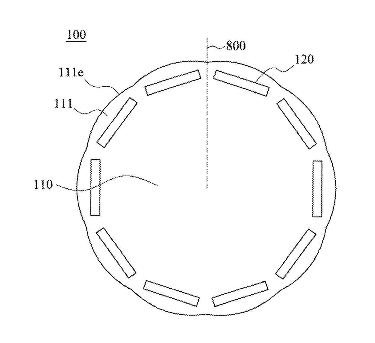
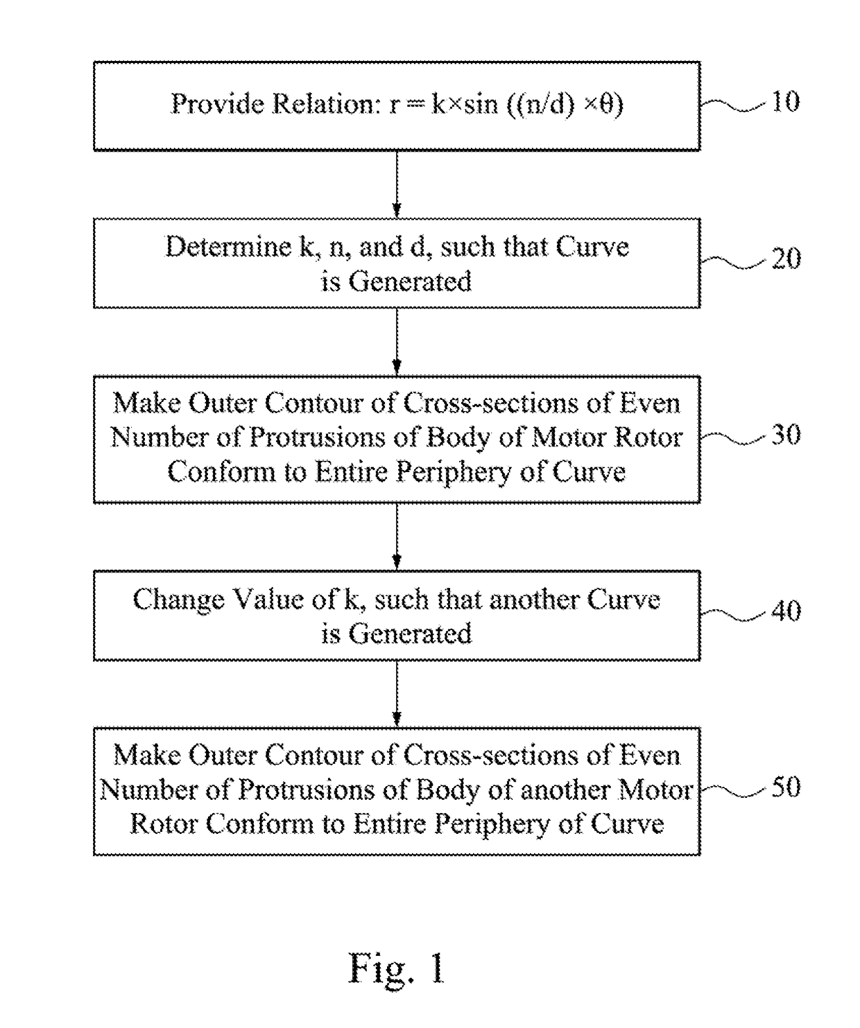
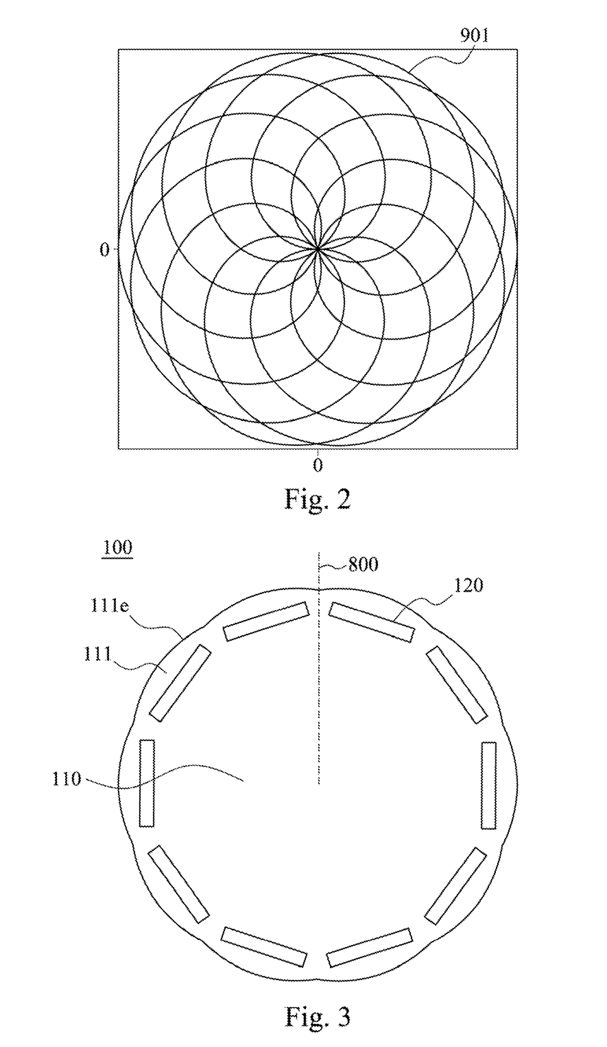
[0033]FIG. 1 is a flowchart of a method for forming a motor rotor 100 according to one embodiment of this disclosure. FIG. 2 is a schematic view showing a relation for protrusions of the motor rotor according to one embodiment of this disclosure. A method for forming motor rotor 100 is provided to simplify the design process of the motor rotor 100.

[0034]At first, as shown in FIG. 1 and FIG. 2, in step 10, a relation is provided:

r=k×sin((n / d)×θ).

[0035]The relation is a rose curve, where (r, θ) is radial and angular coordinates of the polar coordinate system. k, n, and d are adjus...


PUM


Abstract

A motor rotor includes a body and at least one magnet. The body has an even number of protrusions. The outer contour of the cross-sections of the protrusions conforms to at least a portion of the periphery of the relation: r=k×sin ((n / d)×θ), where k is related to the maximum distance between the outer contour of the cross-sections of the protrusions and the center of the body, n is related to the number of protrusions, and d is related to the curvature of the outer contour. The magnet is disposed in the body.

Description

RELATED APPLICATIONS[0001]This application claims priority to Taiwan Application Serial Number 106100204, filed Jan. 4, 2017, which are herein incorporated by reference.BACKGROUNDTechnical Field[0002]The present disclosure relates to a motor rotor and a method for forming the same.Description of Related Art[0003]A motor is an electric machine designed to convert electrical energy into mechanical energy, and then kinetic energy is generated from the mechanical energy, thereby driving another device. Most of electric motors generate energy through magnetic fields and coil current in each of the motors.[0004]The motor includes a stator and a rotor. If the rotational speed of the rotor is the same as the frequency of the supplied alternating current, it is called a synchronous motor. The rotor of the synchronous motor may include an electromagnet or a permanent magnet. The synchronous motor including the permanent magnet is called a permanent magnet synchronous motor. The magnetic field...

Claims


Application Information

Patent Timeline
Patent Type & Authority Applications(United States)
IPC IPC(8): H02K1/27H02K15/03
CPCH02K1/2706H02K2213/03H02K15/03H02K1/27H02K2201/03H02K29/03H02K1/276
Inventor HUNG, SHIH-WEILUO, YIN-JAOYUAN, SHAO-CHUNG
Owner CHICONY POWER TECH CO LTD
Why Eureka
Try Eureka