Coil device

a coil and coil technology, applied in the direction of transformer/inductance coil/winding/connection, transformer/inductance magnetic core, inductance with magnetic core, etc., can solve the problem of difficulty in sufficiently increasing the magnetic coupling between the two conductors, and achieve the effect of simple shape and easy processing

Pending Publication Date: 2022-02-17
TDK CORPARATION
View PDF0 Cites 1 Cited by
  • Summary
  • Abstract
  • Description
  • Claims
  • Application Information

AI Technical Summary

Benefits of technology

[0045]Preferably, a third inclined part inclined so as to be lower outward is formed at a position facing the first outer mounting part on a surface of the first side insulating part, and a fourth inclined part inclined so as to be lower outward is formed at a position facing the second outer mounting part on a surface of the second side insulating part. The first side insulating part can be prevented from interfering (contacting) with the first outer mounting part by forming the third inclined part on the surface of the first side insulating part. Likewise, the second side insulating part can be prevented from interfering (contacting) with the second outer mounting part by forming the fourth inclined part on the surface of the second side insulating part.
[0046]One of the first inner mounting part and the first outer mounting

Problems solved by technology

In the coil device described in Patent Document 1, however, it is difficult to sufficiently increase the magnetic coupling between the two conductors due to th

Method used


Image

  • Coil device
  • Coil device
  • Coil device

Examples


first embodiment

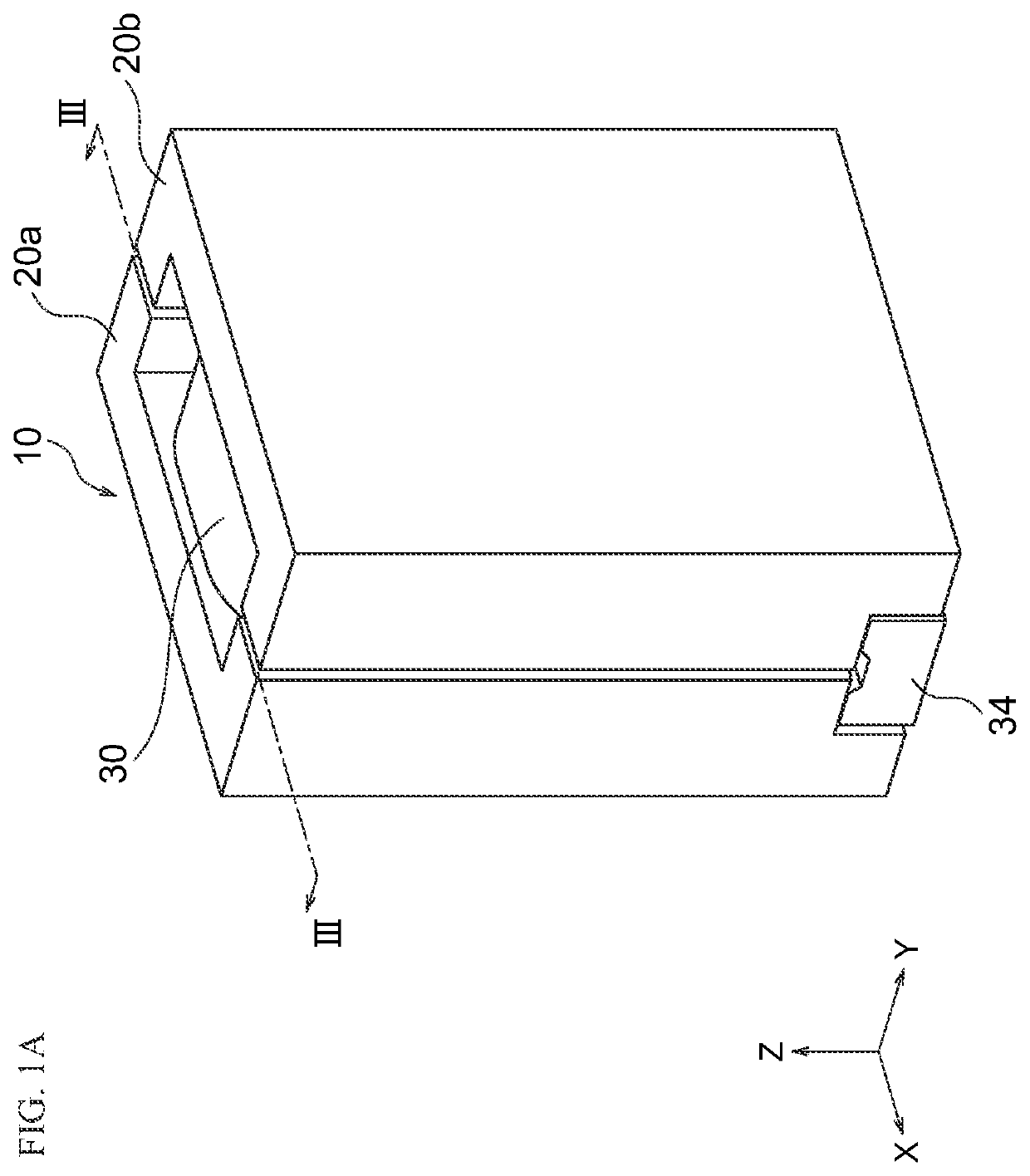
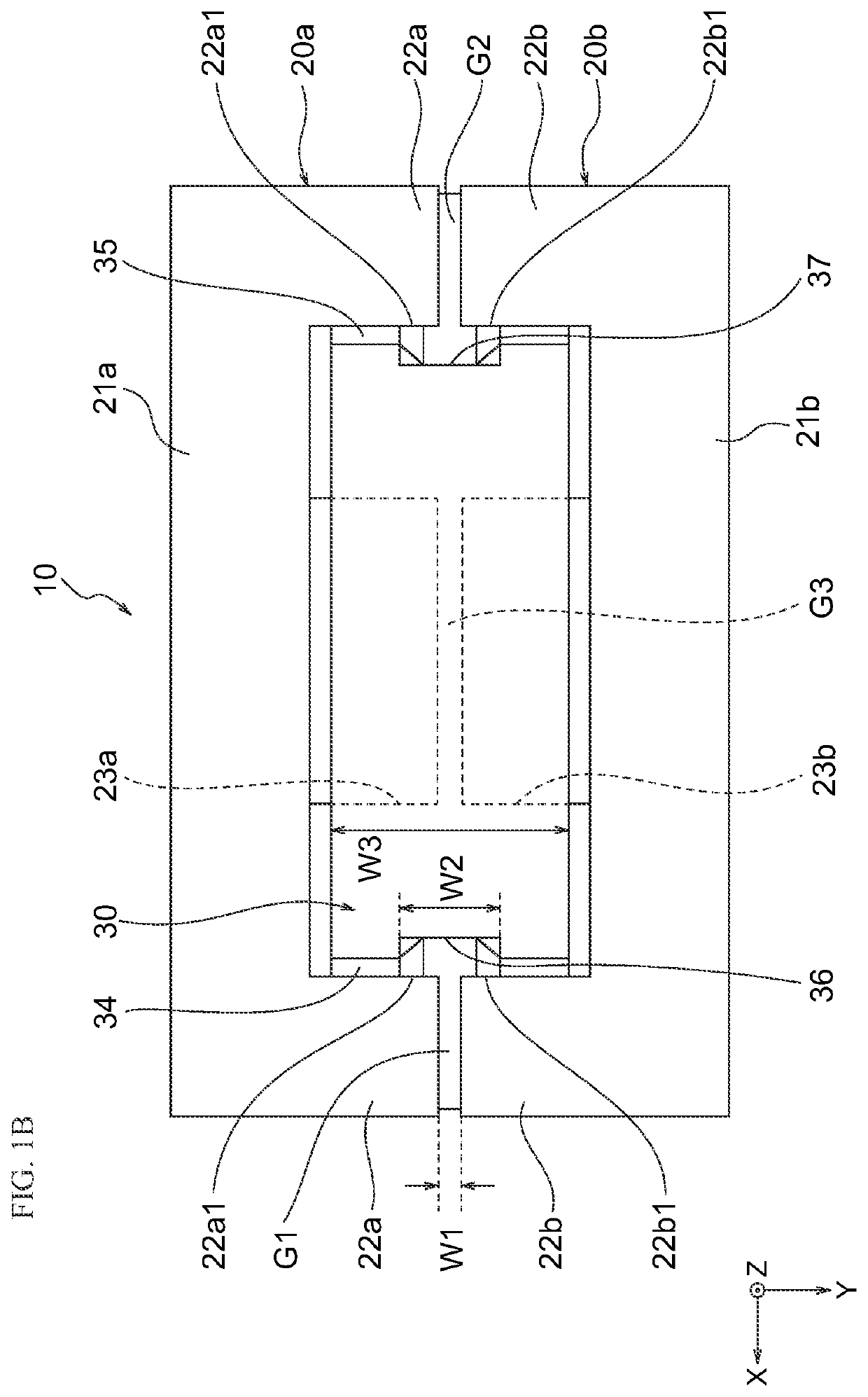
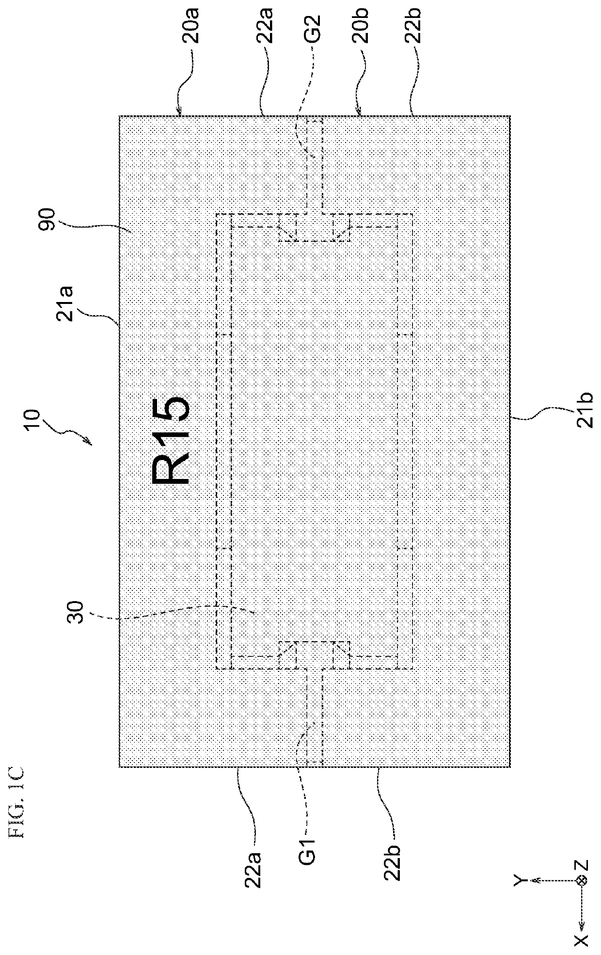
[0091]As shown in FIG. 1A, a coil device 10 according to First Embodiment of the present invention has a substantially rectangular parallelepiped shape and functions as a combined coil used for power supply circuits or so. Preferably, the coil device 10 has a width of 3.0-20.0 mm in the X-axis direction, a width of 3.0-20.0 mm in the Y-axis direction, and a width of 3.0-20.0 mm in the Z-axis direction.

[0092]As shown in FIG. 2, the coil device 10 includes a first core 20a, a second core 20b, a first conductor 30, and a second conductor 40. Either one of the conductors 30 and 40 functions as a primary coil, and the other one of the conductors 30 and 40 functions as a secondary coil. The details of the conductors 30 and 40 are explained below.

[0093]The first core 20a and the second core 20b have the same shape and have what is called an E shape. The first core 20a and the second core 20b are arranged to face each other in the Y-axis direction and are joined with adhesive agent or so. T...

second embodiment

[0165]A coil device 110 according to Second Embodiment of the present invention is different from the coil device 10 according to First Embodiment only in the following matters and has structure and effect similar to those of the coil device 10 according to First Embodiment. In the figures, common members with First Embodiment are given common references and are not explained.

[0166]As shown in FIG. 4A and FIG. 5, the coil device 110 includes a first core 120a, a second core 120b, a first conductor 130, and the second conductor 40. The first core 120a is different from the first core 20a according to First Embodiment in that the first core 120a includes a pair of first outer legs 122a and 122a, but does not include the side grooves 25a and 25b shown in FIG. 2. The first outer legs 122a and 122a are longer in the Z-axis direction by the amount of no arrangement of the side grooves 25a and 25b.

[0167]The second core 120b is different from the second core 20b according to First Embodime...

third embodiment

[0186]A coil device 210 according to Third Embodiment of the present invention is different from the coil device 10 according to First Embodiment only in the following matters and has structure and effect similar to those of the coil device 10 according to First Embodiment. In the figures, common members with First Embodiment and Second Embodiment are given common references and are not explained.

[0187]As shown in FIG. 7, the coil device 210 includes the first core 120a, a second core 220b, the first conductor 30, and a second conductor 240. The second core 220b has a similar shape to the first core 120a.

[0188]As shown in FIG. 8, the second conductor 240 includes a first mounting part 244 and a second mounting part 245. The ends of the mounting parts 244 and 245 (each end of the second conductor 240) stand upward. As shown in FIG. 9, the end surface of the mounting part 244 (245) is disposed with a predetermined interval to the bottom surfaces of the middle legs 23a and 23b of the ...


PUM


Abstract

A coil device includes a first conductor, a second conductor, and a core. The second conductor is disposed inside the first conductor and at least partly extending along the first conductor. The core internally arranges the first conductor and the second conductor. An insulating layer is formed at least between the first conductor and the second conductor.

Description

BACKGROUND OF THE INVENTION[0001]The present invention relates to a coil device used as, for example, an inductor.[0002]As a coil device used as an inductor or so, for example, a coil device described in Patent Document 1 is known. The coil device described in Patent Document 1 includes two conductors and a core for internally arranging the two conductors. In the coil device described in Patent Document 1, the magnetic coupling between the two conductors is increased by forming a region in which no magnetic material is disposed between the two conductors.[0003]In the coil device described in Patent Document 1, however, it is difficult to sufficiently increase the magnetic coupling between the two conductors due to the configuration, and required is a technique that can sufficiently increase the magnetic coupling between the two conductors.[0004]Patent Document 1: JP2007184509 (A)BRIEF SUMMARY OF INVENTION[0005]The present invention has been achieved under such circumstances. It is a...

Claims


Application Information

Patent Timeline
IPC IPC(8): H01F27/32H01F27/24H01F27/02H01F27/28H01F41/12
CPCH01F27/327H01F27/24H01F41/125H01F27/2866H01F27/02H01F27/324H01F27/34H01F27/2847H01F17/04H01F2027/2857H01F27/2852H01F27/323H01F27/306H01F27/266
Inventor WANG, CHENASHIZAWA, SYUNSUGIMOTO, SATOSHI
Owner TDK CORPARATION
Why Eureka
Try Eureka