
Three Axis Aerodynamic Control of Guided Munitions

a technology of guided munitions and control systems, applied in the field of armaments, can solve the problems of low accuracy, unguided munitions are subject to aim errors, wind disturbances, etc., and achieve the effect of improving system accuracy and improving aerodynamic maneuvering performan

Inactive Publication Date: 2008-02-07
BAE SYST INFORMATION & ELECTRONICS SYST INTERGRATION INC
View PDF26 Cites 35 Cited by
  • Summary
  • Abstract
  • Description
  • Claims
  • Application Information

AI Technical Summary

Benefits of technology

The present invention describes a system for improving the maneuvering performance of a munition by using three miniature stepper motors to drive bevel gears attached to three shafts. The motors can be connected through a set of spur gears or a planetary gear assembly to create roll, pitch, and yaw steering commands. This system is robust and can be adapted to conventional MAV airframes to improve aerodynamic maneuvering performance. The canard frame attached to each shaft allows for precise control of the munition's movement.

Problems solved by technology

One of the major disadvantages of mortars is their comparatively low accuracy, and as a result mortars are becoming less effective in today's precision combat environment.
Unguided munitions are subject to aim error and wind disturbances.
These factors, along with other more subtle error sources, may cause the munition to miss the target completely or require many rounds to complete the fire mission due to the resulting large CEP (Circular Error Probability).
Current approaches to guided weapons are expensive and are used on larger, long range weapons.
Mortars are typically unguided or guided by an expensive G&C (Guidance and Control) system.
The cost is high for current guided mortars and unguided mortars may have poor accuracy.
Also, unguided mortars may result in unacceptable collateral damage, excess cost due to the large number of rounds required to blanket the target area, and may expose the mortar crew to counterbattery fire due to the large time required to drop the necessary shells to saturate the target.

Method used


Image

  • Three Axis Aerodynamic Control of Guided Munitions
  • Three Axis Aerodynamic Control of Guided Munitions
  • Three Axis Aerodynamic Control of Guided Munitions

Examples


first embodiment

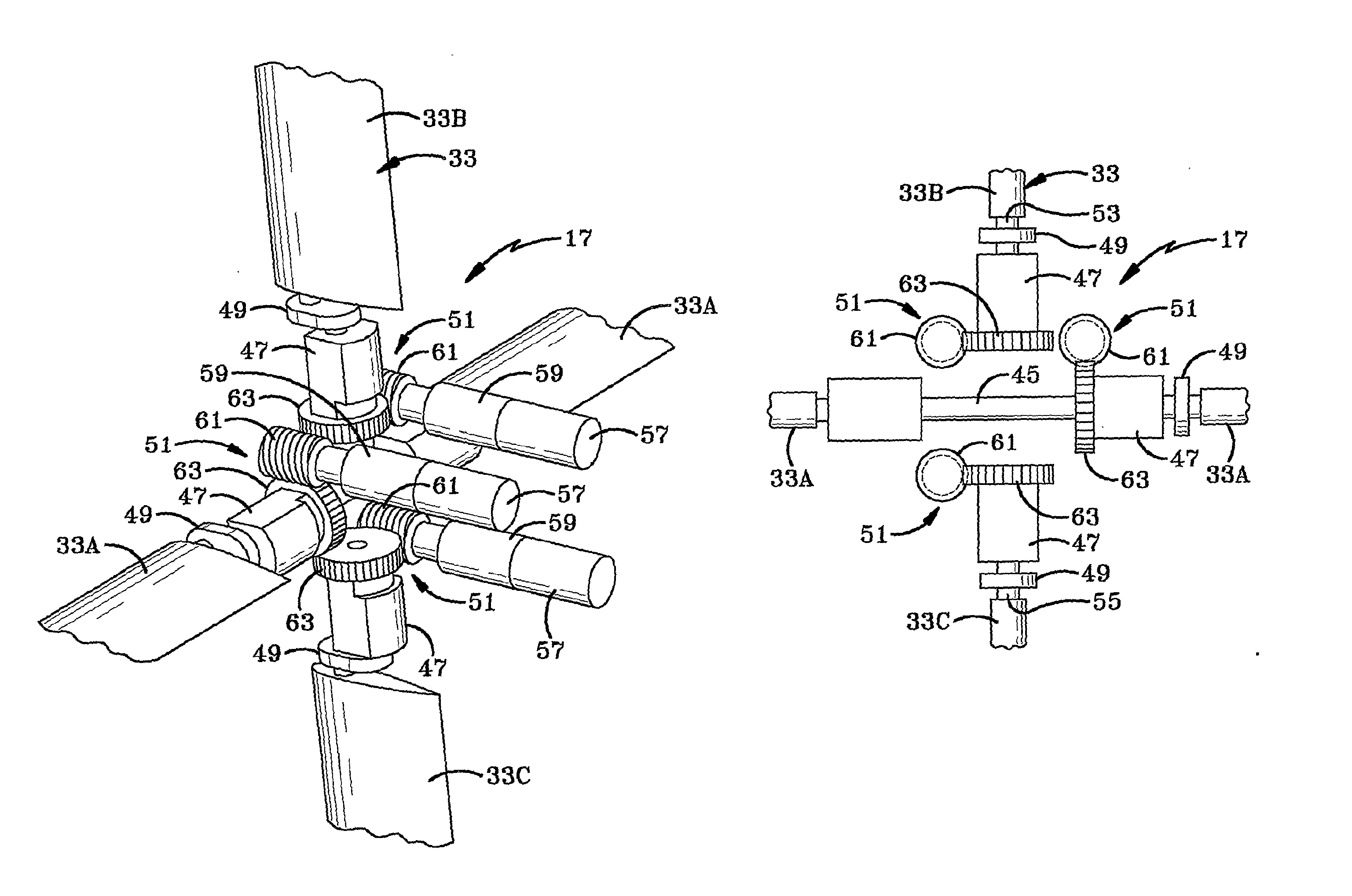
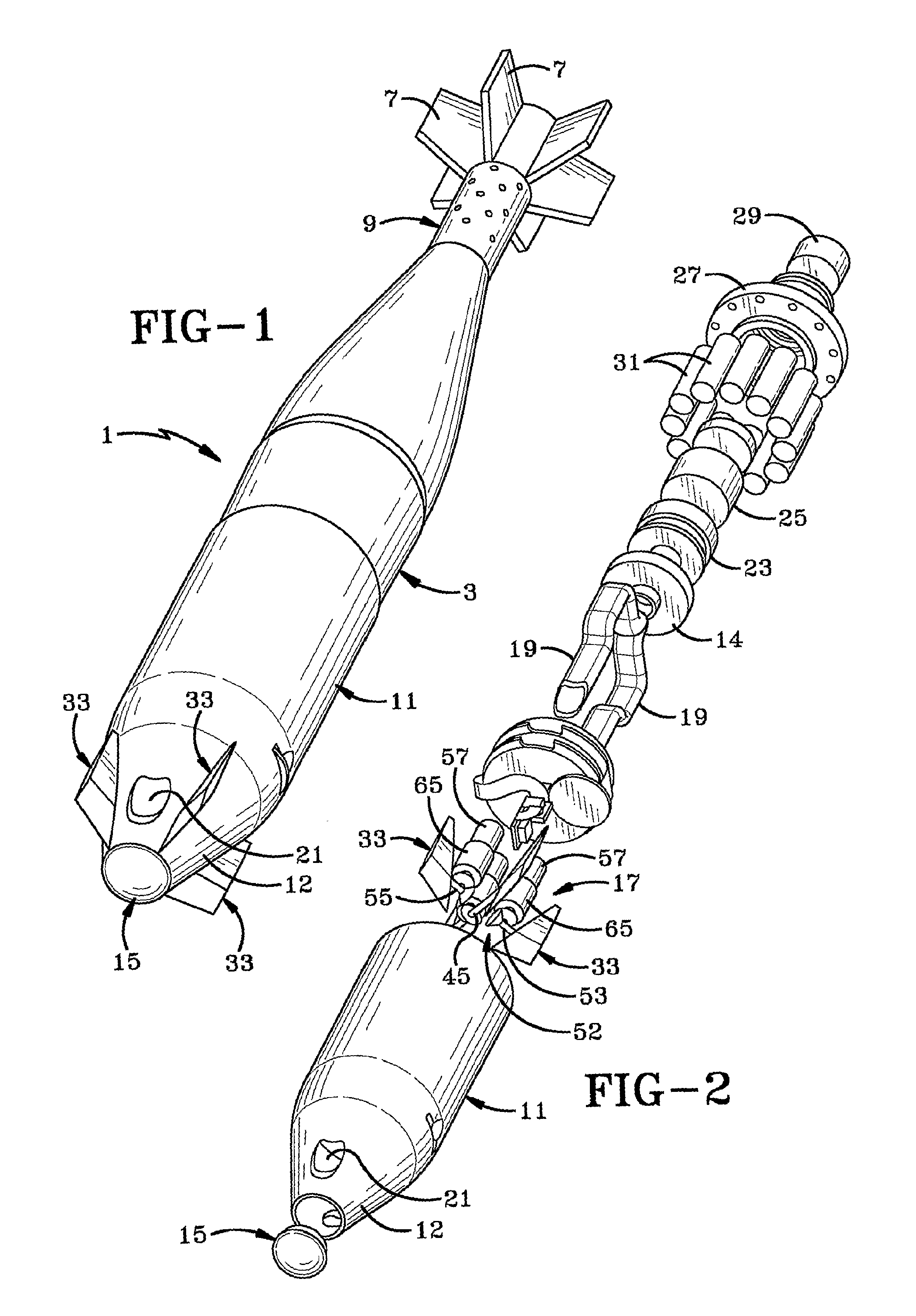
[0032] the three axis control system 17 is shown in detail in FIGS. 6 and 6A. System 17 includes four canards 33, an example of which is shown in FIGS. 5 and 5A. Canards 33 preferably are identical or very similar to each other, each having a double wedge configuration consisting of a first wedge 35 and a second wedge 37. Each wedge is formed with symmetrical opposed surfaces which taper inwardly outwardly from a junction 41 in which is located a pivot 43. The junction 41 and pivot 43 are located at the thickest portion of the canard which also is the longitudinal center of pressure of the canard, which provides for torque balanced aerodynamic surfaces for the canard.

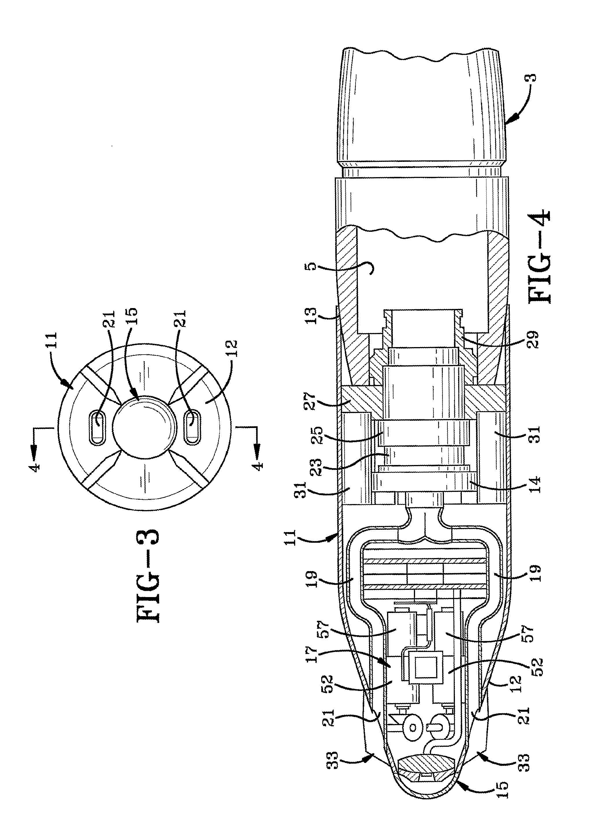
[0033] Referring to FIGS. 6 and 6A, two of the canards indicated at 33A, are connected to a common shaft 45, each through a wing pivot lock 47 and a wing fold pivot 49. Lock 47 and pivot 49 enable the canard to be retracted against nose 11 enabling certain munitions to be launched from a mortar launcher, afterwhich the ...

second embodiment

[0036] In a second embodiment as shown in FIGS. 7, 7A and 7B, a modified gear assembly indicated generally at 52, includes stepper motors 57 which are connected to the respective canard shafts through a spur reduction gear 65 or 65A, each preferably having a 30 / 1 zero backlash reduction drive. The spur reduction gears in turn are connected to a first bevel gear 67 which engages and drives a second bevel gear 68 attached to a respective one of the canard shafts.

[0037] Thus, drive motors 57, which preferably are stepper motors, can be connected by various gear assemblies, such as gear assemblies 51 and 52 to the canards, which if desired will be through a pivot lock 47 and fold pivot 49, and in another embodiment directly to the canards. In either construction the gear assemblies and drive motors will rotate the canards about their pivots 43 to control the pitch, roll and yaw movement of the munition body after passing through apogee and in its descent toward a target along a ballisti...


PUM


Abstract

An apparatus for 3-axis aerodynamic control of multi-caliber bodies comprising three shafts each having at least one canard; bevel gears attached to said shafts; and a set of three miniature stepper motors, each driving a zero backlash spur assembly attached to the drive bevel gears.

Description

CROSS REFERENCE TO RELATED APPLICATION [0001] This application claims rights under 35 USC 119(e) from U.S. application Ser. No. 60 / 650,705, filed Feb. 7, 2005; the contents of which are incorporated herein by reference.BACKGROUND OF THE INVENTION [0002] 1. Field of the Invention [0003] The present invention relates to armaments and more particularly to guided munitions. Even more particularly, the invention relates to a three axis control system and mechanism for guided mortar shells or for other small aerodynamic bodies. [0004] 2. Background Information [0005] Mortars are one of the most commonly employed weapons in a ground combat unit. The traditional role of mortars has been to provide close and continuous fire support for maneuvering forces. Military history has repeatedly demonstrated the effectiveness of mortars. Their rapid, high-angle, plunging fires are invaluable against dug-in enemy troops and targets in defilade, which are not vulnerable to attack by direct fires. One o...

Claims


Application Information

Patent Timeline
Patent Type & Authority Applications(United States)
IPC IPC(8): F42B10/02
CPCF42B10/64
Inventor CARLSON, MARK A.ZEMANY, PAUL D.MAYNARD, JOHN A.
Owner BAE SYST INFORMATION & ELECTRONICS SYST INTERGRATION INC
Learn More