Differential signaling system and method of controlling skew between signal lines thereof

a signaling system and signal line technology, applied in the field of differential signaling system and method of controlling skew between signal lines thereof, can solve the problems of differential noise, common mode noise which is added, and reduces the effectiveness of common mode noise rejection by differential amplifiers, so as to reduce the effectiveness of common mode noise rejection and degenerate the signal/noise ratio

Inactive Publication Date: 2008-02-07
HITACHI CABLE
View PDF5 Cites 7 Cited by
  • Summary
  • Abstract
  • Description
  • Claims
  • Application Information

AI Technical Summary

Benefits of technology

[0007] However, if a variable delay circuit is provided on the input of the differential amplifier of the receiver circuit in order to control the skew as described in Patent Document 1, common mode noise which is added just before the receiver circuit is converted to differential noise by the differential amplifier. This reduces the effectiveness of common mode noise rejection by the differential amplifier. Especially, at the immediate upstream side of the receiver circuit, the signal is vulnerable to noise since the signal amplitude has reduced due to loss along the cable or board, resulting in a degenerated signal / noise ratio.

Problems solved by technology

However, if a variable delay circuit is provided on the input of the differential amplifier of the receiver circuit in order to control the skew as described in Patent Document 1, common mode noise which is added just before the receiver circuit is converted to differential noise by the differential amplifier.
This reduces the effectiveness of common mode noise rejection by the differential amplifier.
Especially, at the immediate upstream side of the receiver circuit, the signal is vulnerable to noise since the signal amplitude has reduced due to loss along the cable or board, resulting in a degenerated signal / noise ratio.

Method used


Image

  • Differential signaling system and method of controlling skew between signal lines thereof
  • Differential signaling system and method of controlling skew between signal lines thereof
  • Differential signaling system and method of controlling skew between signal lines thereof

Examples


embodiment 1

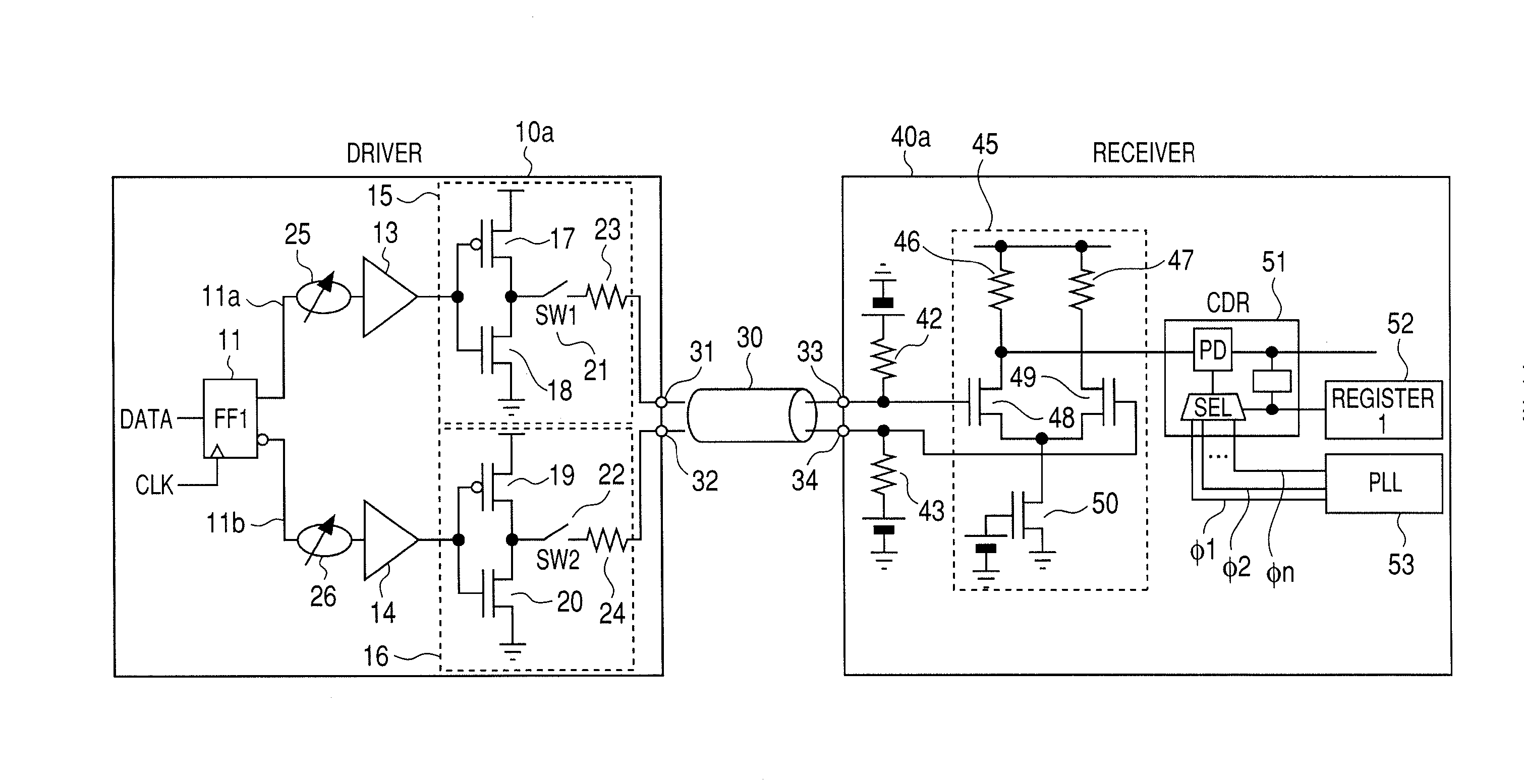
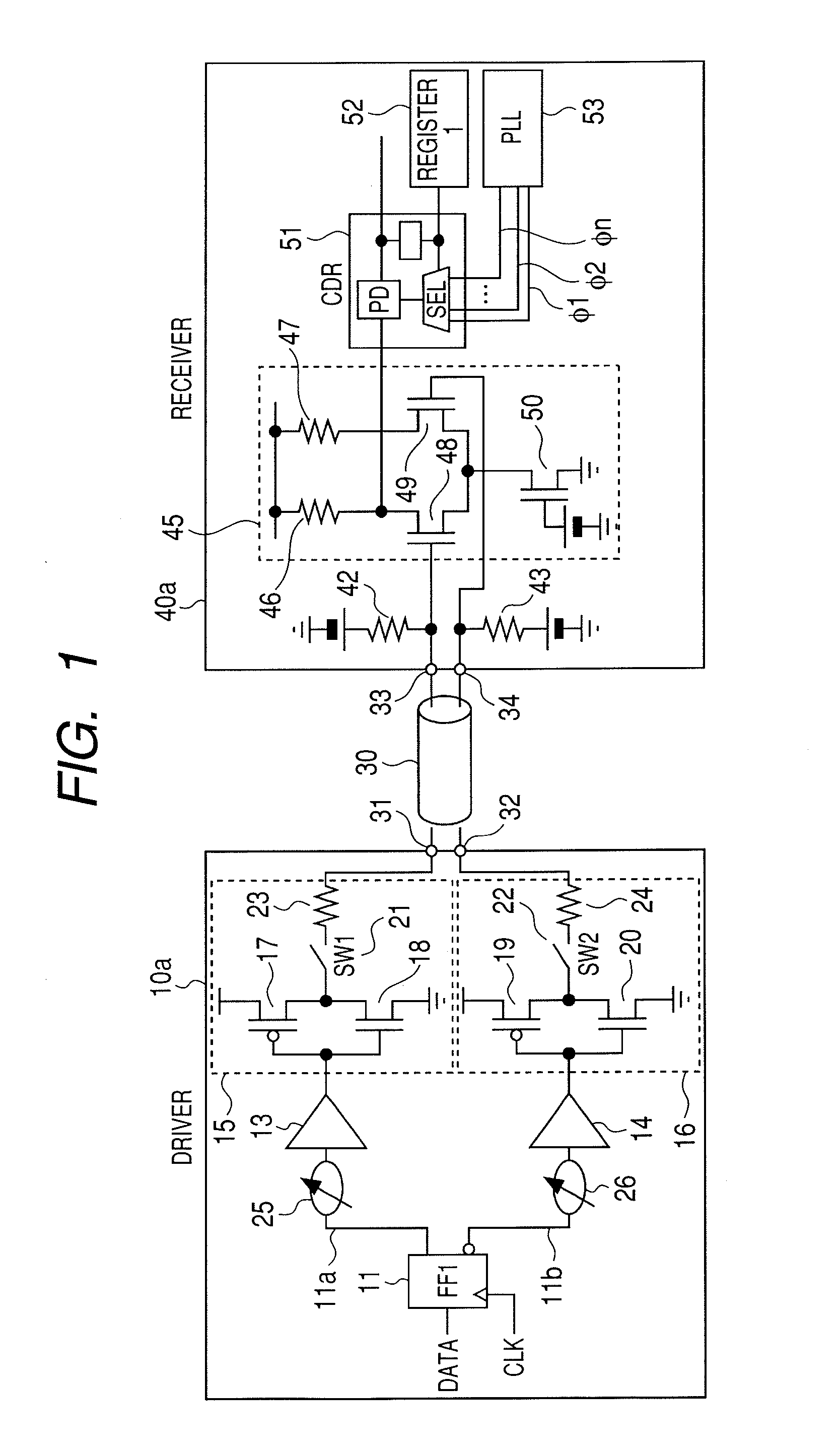
[0035]FIG. 1 is a circuit diagram showing a differential signaling system according to a first embodiment of the present invention, which comprises a driver circuit and a receiver circuit and constitutes part of a connectorized cables an information processing apparatus or the like.

[0036] The driver circuit 10a according to the first embodiment comprises: an output buffer 15; an output buffer 16; a preamplifier 13 for driving the output buffer 15; a preamplifier 14 for driving the output buffer 16; variable delay circuits 25 and 26; and a flip flop (FF) circuit 11 to which DATA and a CLK are input and which has an output 11a and an output 11b that is obtained by inversing the output 11a. The output buffer 15 comprises: a PMOS transistor 17 and a NMOS transistor 18 which are connected in series between a dc voltage and the ground; and a switch 21 and a termination resistor 23 which are connected in series between the drain of the PMOS transistor 17 or the drain of the NMOS transisto...

second embodiment

[0054]FIG. 7 is a circuit diagram showing a differential signaling system according to a second embodiment of the present invention, which comprises a driver circuit and a receiver circuit and constitutes part of a connectorized cable, an information processing apparatus or the like.

[0055] The driver circuit 10b of the second embodiment comprises: a differential output buffer 70; a differential output buffer 80; a preamplifier 13 for driving the output buffer 70; a preamplifier 14 for driving the output buffer 80; variable delay circuits 25 and 26; and a flip flop (FF) circuit 11 which receives an input DATA and an input CLK and provides an output 11a and an output 11b obtained by inversing the output 11a. The differential output buffer 70 comprises: NMOS transistors 73 and 74 whose sources are connected; resistors 71 and 72 which are respectively connected between the drains of the NMOS transistors 73 and 74 and a dc voltage; a NMOS transistor 75 which serves as a constant current...

third embodiment

[0061]FIG. 8 is a circuit diagram showing a third differential signaling system embodiment of the present invention which comprises a driver circuit and a receiver circuit and constitutes part of a connectorized cable, an information processing apparatus or the like.

[0062] The driver circuit 10c comprises: an output buffer 15 comprising a PMOS transistor 17 and a NMOS transistor 18 which are connected in series and a termination resistor 23; an output buffer 16 comprising a PMOS transistor 19 and a NMOS transistor 20 which are connected in series and a termination resistor 24; a preamplifier 13 for driving the output buffer 15; a preamplifier 14 for driving the output buffer 16; variable delay circuits 25 and 26; and a flip flop (FF) circuit 11 to which DATA and a CLK are input and provides an output 11a and an output 11b obtained by inversing the output 11a. The output buffers 15 and 16 of the third embodiment may be constructed of differential output buffers such as those 70 and ...


PUM


Abstract

The present invention provides a differential signaling system comprising: a driver circuit that transmits a differential signal; a receiver circuit that receives the differential signal; and two or more signal lines used for the differential signal to be transmitted by the driver circuit and received by the receiver circuit, wherein the driver circuit gives an arbitrary time lag between the two signals that form the differential signal before transmitting them.

Description

BACKGROUND OF THE INVENTION [0001] 1. Field of the Invention [0002] The present invention relates to a differential signaling system which uses at least two signal wires to connect a driver circuit and a receiver circuit and transmits a small amplitude signal between at high rates of several hundred Mbps or higher. The invention also relates to a method of controlling the skew between the signal lines of such a differential signaling system, and to a connectorized cable and an information processing apparatus each of which is provided with such a differential signaling system. [0003] 2. Description of the Related Art [0004] Due to high immunity to noise, especially to common mode noise, transmission of a differential signal by using two signal wires is commonly employed for transmitting a small amplitude signal at high rates of several hundred Mbps or higher. [0005] However, differential signaling poses a problem that raising the transmission rate increases the effect of the propaga...

Claims


Application Information

Patent Timeline
Patent Type & Authority Applications(United States)
IPC IPC(8): H03K3/00H01R13/66H03K5/12
CPCH04L25/0272H01L2224/45565H01L2924/01006H01L2924/01015H01L24/46H01L24/45H01L2224/48137H01L2224/45572H01L2224/48092H01L2924/3025H01L2924/00H01L2924/00011H01L2924/00014H01L2924/14H01L2224/45099H01L2224/43
Inventor CHUJO, NORIOMURAOKA, SATOSHI
Owner HITACHI CABLE
Why Eureka
Try Eureka