

Antenna Device
- Summary
- Abstract
- Description
- Claims
- Application Information
AI Technical Summary
Benefits of technology
Problems solved by technology
Method used
Image

Examples
Embodiment Construction
[0018]In this text the case of a traditional base station and a traditional mobile phone will be used to describe the invention. As the progress of consumer electronics is making the difference between a phone, a small handheld computer, or a card inserted in a portable or stationary computer unclear, it should be understood that the invention is not limited to only one of those cases.
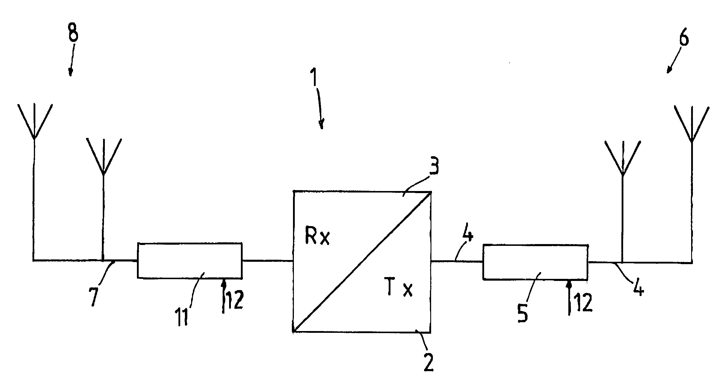
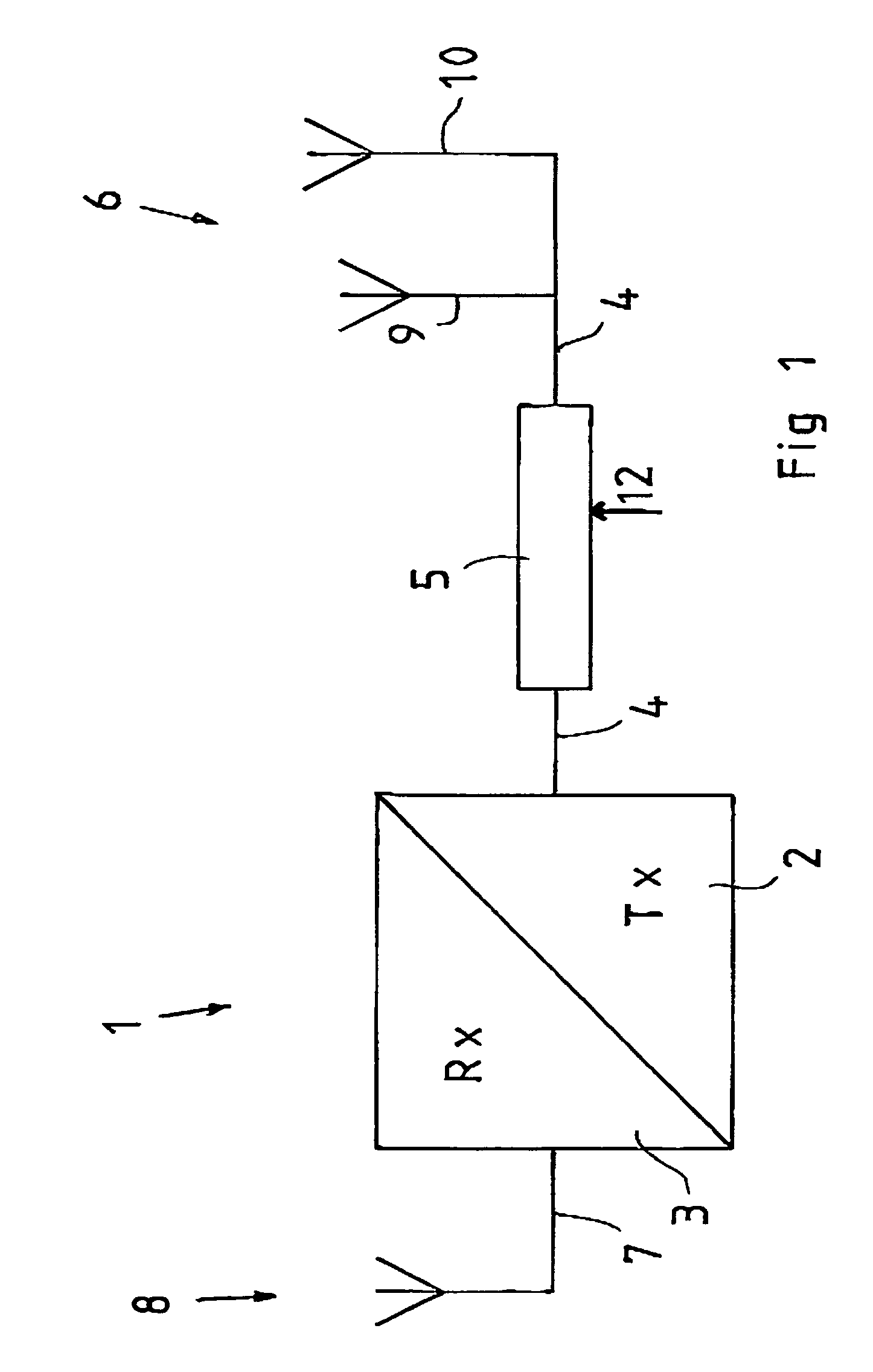
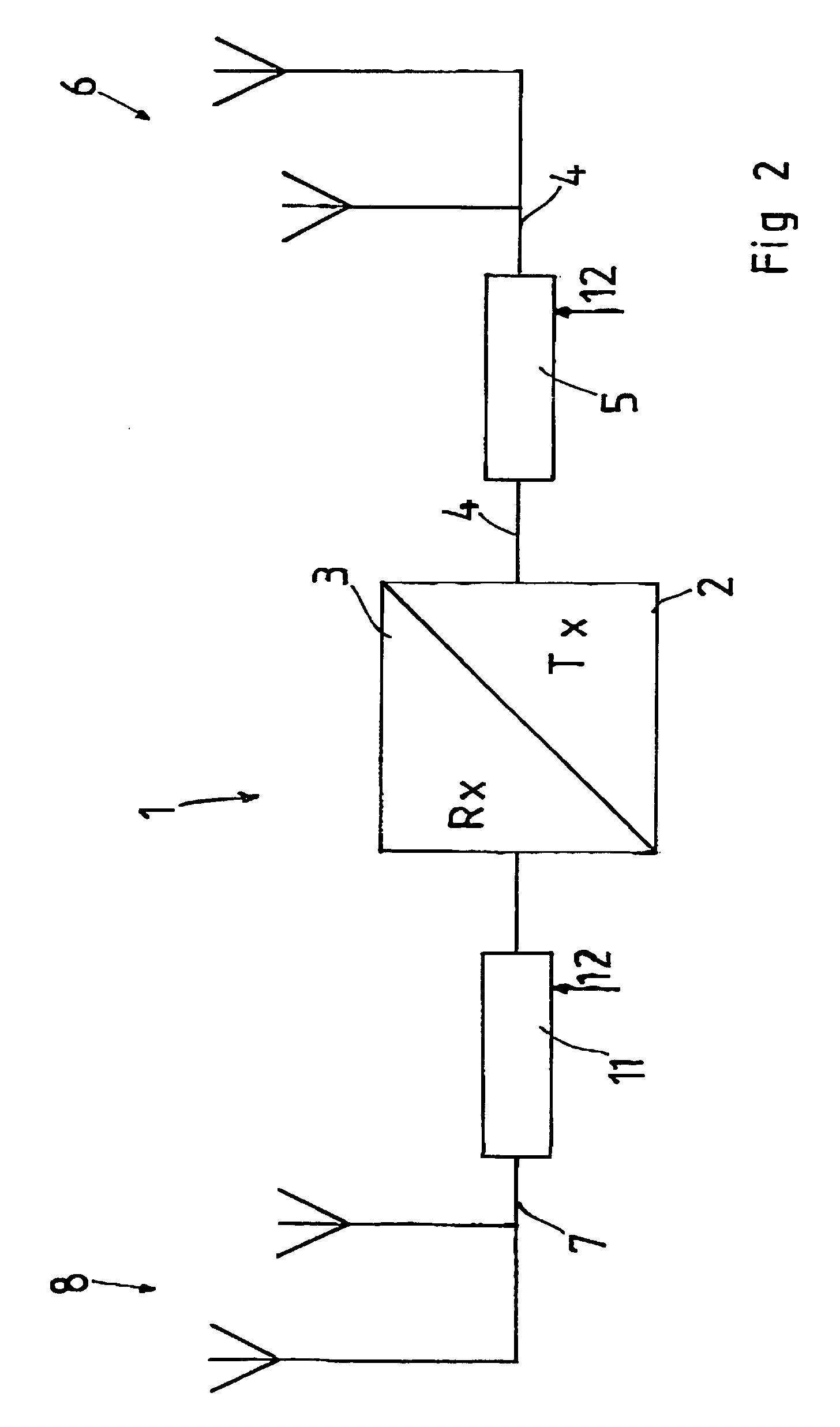
[0019]In the accompanying Drawing, reference numeral 1 relates to a radio unit which has a transmitter subunit 2 and a receiver subunit 3. From the transmitter subunit 2, a first feeding line 4 extends to an active or adaptive matching network 5. The matching network 5 is connected to a first antenna element 6 which is thus designed so as to radiate the energy that the transmitter subunit 2 produces.
[0020]The receiver subunit 3 in the radio unit 1 is connected via a second feeding line 7 to a second antenna element 8. Both the second feeding line 7 and the second antenna element 8 are separate and disc...
PUM
 Abstract
Description
Claims
Application Information