Transflective liquid crystal display device

a liquid crystal display device and transflective technology, applied in non-linear optics, instruments, optics, etc., can solve the problems of unfavorable rise of drive voltage and insufficient reflectivity, and achieve the effect of improving the reflectivity of the transflective liquid crystal display devi

Inactive Publication Date: 2008-02-07
PANASONIC LIQUID CRYSTAL DISPLAY CO LTD +1
View PDF5 Cites 22 Cited by
  • Summary
  • Abstract
  • Description
  • Claims
  • Application Information

AI Technical Summary

Benefits of technology

[0010]The present invention has been made in order to address the problem of the conventional technology as described above and provides a technology which can improve the reflectivity of the transflective liquid crystal display device.
[0018]According to the embodiments of the present invention, it is possible to improve the reflectivity of the transflective liquid crystal display device.

Problems solved by technology

However, in the IPS mode, when the cell gap length is narrowed, the drive voltage unfavorably rises.
Therefore, the voltage-reflectivity characteristics of the reflective unit are shifted to the high-voltage side compared with the voltage-transmissivity characteristics of the transmissive unit, and sufficient reflectivity can not be obtained.
This fact may cause a problem.

Method used


Image

  • Transflective liquid crystal display device
  • Transflective liquid crystal display device
  • Transflective liquid crystal display device

Examples


embodiment 1

[0073]The transflective liquid crystal display device according to Embodiment 1 is different from the transflective liquid crystal display device shown in FIG. 1 with respect to the shape of the pixel electrode (PIX), however other structure is the same as that of the transflective liquid crystal display device shown in FIG. 1. Therefore, the transflective liquid crystal display device according to Embodiment 1 is hereafter explained focusing on the difference with the transflective liquid crystal display device shown in FIG. 1.

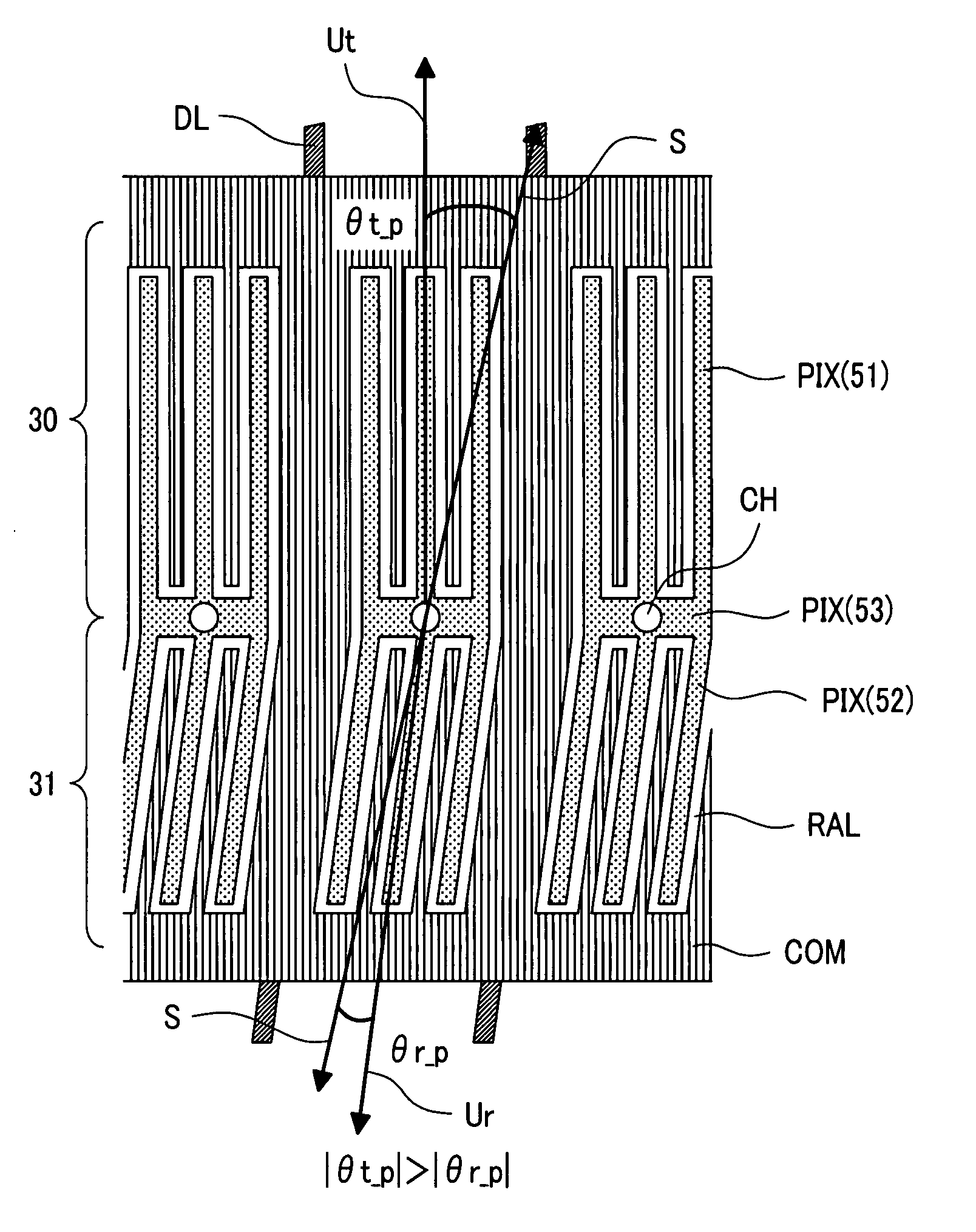
[0074]FIG. 12 shows the relationship between the initial liquid crystal alignment direction (S) and the projection direction of the pixel electrode (PIX), when the positive-type liquid crystal is used in the transflective liquid crystal display device according to Embodiment 1 of the present invention.

[0075]When a narrower angle among angles formed by the initial liquid crystal alignment direction (S) of the liquid crystal layer (LC) and the projection direct...

embodiment 2

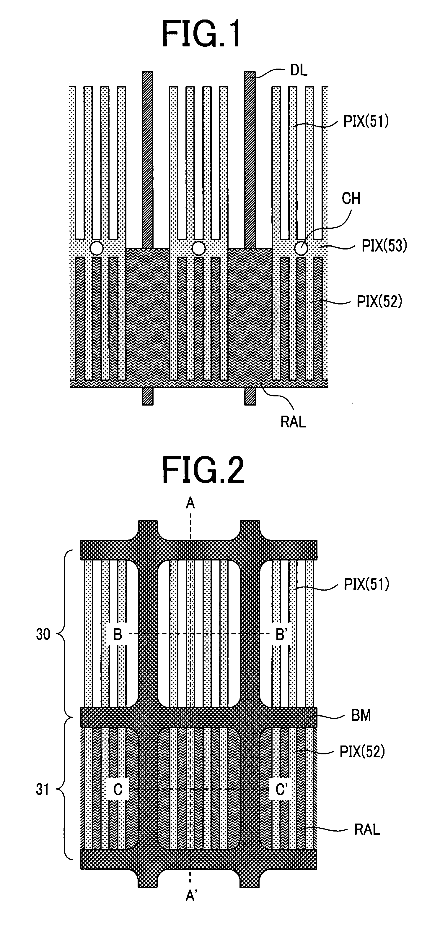
[0091]FIG. 16 is a top view illustrating one sub-pixel on the side of a TFT substrate in a transflective liquid crystal display device according to Embodiment 2 of the present invention. FIG. 17 is a top view illustrating one sub-pixel when the TFT substrate of FIG. 16 and a CF substrate are superposed. FIG. 18 is a cross-sectional view illustrating a cross-sectional structure taken along the line D-D′ of FIG. 17.

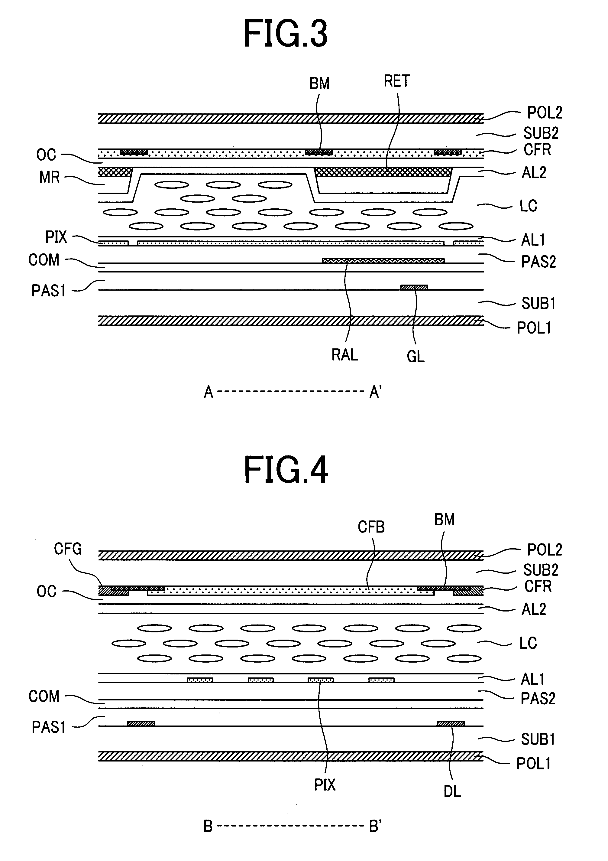
[0092]In addition, the cross-sectional view taken along the line A-A′ and the cross-sectional view taken along the line B-B′ of FIG. 17 are the same as in FIG. 3 and FIG. 4, respectively.

[0093]The transflective liquid crystal display device of Embodiment 2 possesses basically the same structure as that of the above-mentioned Embodiment 1, with the exception of the following structure.

[0094]Namely, in the transflective liquid crystal display device according to Embodiment 2, in concert with the fact that the pixel electrode (PIX) (the linear section 52) of the reflective uni...

embodiment 3

[0095]FIG. 19 is a top view of one sub-pixel of the transflective liquid crystal display device according to Embodiment 3 of the present invention. FIG. 20 is a cross-sectional view illustrating a cross-sectional structure taken along the line E-E′ of FIG. 19.

[0096]In addition, the cross-sectional view taken along the line A-A′ and the cross-sectional view taken along the line B-B′ of FIG. 19 are the same as in FIG. 3 and FIG. 4, respectively.

[0097]The transflective liquid crystal display device of Embodiment 3 possesses basically the same structure as that of the above-mentioned Embodiment 2, with the exception of the following structure.

[0098]That is, in the transflective liquid crystal display device of Embodiment 3, the light blocking film (BM) in the vertical direction (the projection direction of the video line (DL)) of the reflective unit 31 is removed, in other words, the light blocking film (BM) is not formed in the boundary area between sub-pixels which adjoin along with t...


PUM

PropertyMeasurementUnit
gap widthaaaaaaaaaa
gap widthaaaaaaaaaa
drive voltage Vmaxaaaaaaaaaa

Abstract

In a transflective liquid crystal display device, assuming that a narrower angle among angles formed by the initial liquid crystal alignment direction of a liquid crystal layer, and the projection direction of a pixel electrode of a transmissive unit is Et and that a narrower angle among angles formed by the initial liquid crystal alignment direction of the liquid crystal layer, and the projection direction of a pixel electrode of a reflective unit is θr, (1) when the liquid crystal layer possesses a positive-type liquid crystal, the relation of θt>θr is satisfied, and (2) when the liquid crystal layer possesses a negative-type liquid crystal, the relation of θr>θt is satisfied. The relations are satisfied by slanting or bending at least one of the pixel electrodes, and the reflectivity is improved.

Description

CLAIM OF PRIORITY[0001]The present application claims priority from Japanese Application JP 2006-212236 filed on Aug. 3, 2006, the content of which is hereby incorporated by reference into this application.BACKGROUND OF THE INVENTION[0002](1) Field of the Invention[0003]The present invention relates to transflective liquid crystal display devices, more particularly, to an art which is effective in applying the transflective liquid crystal display device to an IPS (In Plane Switching) mode.[0004](2) Description of the Related Art[0005]A transflective liquid crystal display device which has a transmissive unit and a reflective unit in one sub-pixel is used as a display for portable devices.[0006]The transflective liquid crystal display device employs a vertical electric field system in which electric field is impressed to a liquid crystal interposed between a pair of substrates, in the direction perpendicular to the substrate plane of the pair of substrates, thereby driving the liquid...

Claims


Application Information

Patent Timeline
Patent Type & Authority Applications(United States)
IPC IPC(8): G02F1/1335
CPCG02F1/133512G02F2201/122G02F1/134363G02F1/133555
Inventor IGETA, KOICHITANNO, JUNJIIMAYAMA, HIROTAKANAGATA, TETSUYA
Owner PANASONIC LIQUID CRYSTAL DISPLAY CO LTD
Why Eureka
Try Eureka