High Efficiency Light Source Using Solid-State Emitter and Down-Conversion Material

a technology of solid-state emitters and light sources, applied in lighting applications, instruments, with built-in power, etc., can solve the problems of decreasing visible spectra, inefficient current state of the art led technology, and inefficient return in visible spectra

Active Publication Date: 2008-02-07
RENESSELAER POLYTECHNIC INST
View PDF99 Cites 130 Cited by
  • Summary
  • Abstract
  • Description
  • Claims
  • Application Information

AI Technical Summary

Problems solved by technology

Due to their long operation (burn) time and low power consumption, solid state light emitting devices frequently provide a functional cost benefit, even when their initial cost is greater than that of conventional lamps.
Current state of the art LED technology is inefficient in the visible spectra.
More particularly, the LED device becomes less efficient when heated to a temperature greater than 100° C., resulting in a declining return in the visible spectra.

Method used


Image

  • High Efficiency Light Source Using Solid-State Emitter and Down-Conversion Material
  • High Efficiency Light Source Using Solid-State Emitter and Down-Conversion Material
  • High Efficiency Light Source Using Solid-State Emitter and Down-Conversion Material

Examples


Embodiment Construction

[0056]Although the invention is illustrated and described herein with reference to specific embodiments, the invention is not intended to be limited to the details shown. Rather, various modifications may be made in the details within the scope and range of equivalents of the claims and without departing from the invention.

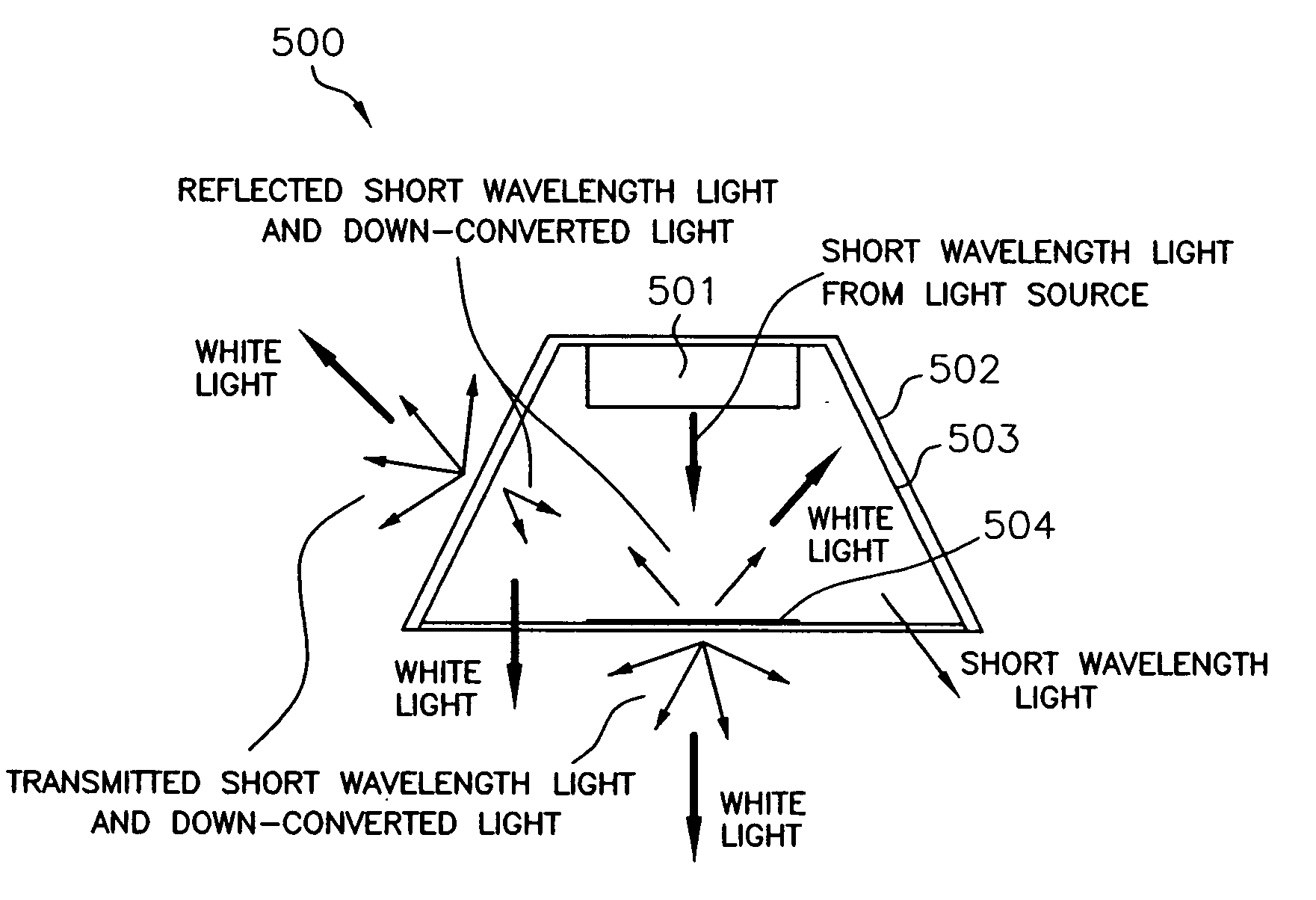
[0057]The inventors have discovered that the performance of phosphor converted LEDs is negatively affected when placing the down-conversion phosphor close to the LED die. Poor performance is mainly due to the fact that the phosphor medium surrounding the die behaves like an isotropic emitter, and some portion of the light that reflects back towards the die circulates between the phosphor layer, the die, and the reflector cup. As a result, the light coupled back into the device increases the junction temperature, thus reducing system efficacy and increasing the yellowing of the encapsulant. All of these factors reduce the light output over time.

[0058]The literature...


PUM


Abstract

A light emitting apparatus includes a source of light for emitting light; a down conversion material receiving the emitted light, and converting the emitted light into transmitted light and backward transmitted light; and an optic device configured to receive the backward transmitted light and transfer the backward transmitted light outside of the optic device. The source of light is a semiconductor light emitting diode, a laser diode (LD), or a resonant cavity light emitting diode (RCLED). The down conversion material includes one of phosphor or other material for absorbing light in one spectral region and emitting light in another spectral region. The optic device, or lens, includes light transmissive material.

Description

RELATED APPLICATION[0001]This application claims the benefit of priority to U.S. Provisional Application Ser. No. 60 / 568,373, filed May 5, 2004 and to U.S. Provisional Application No. 60 / 636,123 filed Dec. 15, 2004, the contents of each being incorporated by reference herein.BACKGROUND OF THE INVENTION[0002]Solid state light emitting devices, including solid state lamps having light emitting diodes (LEDs) and resonant cavity LEDs (RCLEDs) are extremely useful, because they potentially offer lower fabrication costs and long term durability benefits over conventional incandescent and fluorescent lamps. Due to their long operation (burn) time and low power consumption, solid state light emitting devices frequently provide a functional cost benefit, even when their initial cost is greater than that of conventional lamps. Because large scale semiconductor manufacturing techniques may be used, many solid state lamps may be produced at extremely low cost.[0003]In addition to applications s...

Claims


Application Information

Patent Timeline
Patent Type & Authority Applications(United States)
IPC IPC(8): F21V7/00F21K99/00F21V8/00F21V9/40G02B6/00G02B17/08H01L33/58
CPCF21K9/00G02B6/0003G02B6/0031G02B6/0033F21Y2101/02G02B19/0052G02B19/0028G02B19/0061H01L33/58F21K9/64F21Y2115/10
Inventor NARENDRAN, NADARAJAHGU, YIMINFREYSSINIER, JEAN PAUL
Owner RENESSELAER POLYTECHNIC INST
Why Eureka
Try Eureka