Air duct for vehicle air conditioning and air conditioner for vehicle

a technology for air ducts and vehicles, applied in mechanical devices, roofs, transportation and packaging, etc., can solve the problems of noise generation while the blower is blowing, noise is emitted to the vehicle compartment, and there is no specific application example of interference type sound attenuator, so as to reduce the generation of unsteady flow, reduce wind roar, and reduce noise emitted

Active Publication Date: 2008-02-07
DENSO CORP
View PDF3 Cites 39 Cited by
  • Summary
  • Abstract
  • Description
  • Claims
  • Application Information

AI Technical Summary

Benefits of technology

[0051] In a duct, in which the bending section does not include the first passage and the second passage, different from the present invention, an unsteady flow may be locally generated when conditioned air passes through the bending section of the duct, if the length of the downstream-side duct section in the flow direction of the conditioned air is 500 mm or less, as in Comparative Example 2 of FIG. 12. In accordance with the present invention, however, it is possible to suppress generation of an unsteady flow in the bending section, and to reduce a wind roar occurring at grilles due to pulsations caused by a local high flow velocity or an unbalanced flow velocity distribution. Accordingly, the length of the downstream-side duct section in the flow direction of the conditioned air is more effective when it is about 500 mm or less.
[0052] The bending section may be arranged just before the vehicle compartment outlet port in the flow direction of the conditioned air, and has a bending angle of about in a range of 45° to 180°, in order to reduce noise emitted from the vehicle compartment outlet port into the vehicle compartment and a suppression of an unsteady flow of conditioned air discharged from the vehicle compartment outlet port.
[0053] According to an eleventh aspect of the present invention, the bending section (3) may be configured such that difference (L1−L2) between passage lengths of the first passage and the second passage (6, 7) extending through centers

Problems solved by technology

As a result, noise generated due to a sound of the blower and a flow of air in the air conditioning body unit is propagated through the vehicle air-conditioning air duct, so that the noise is emitted to the vehicle compartment.
In Japanese Laid-open Patent Publication No. 2004-196180, however, there is no disclosure as to a specific application example of an interference type sound attenuator to an air duct for vehicle air conditioning.
For example, such noise is generated while the blower operates or while air passes through an evaporator, etc.
In this case, however, there is a problem in that the effect decreases on noise reduction of a low frequency band of 2 kHz or less.
Meanwhile, since sound waves have directionality, it is difficult for sound waves to travel in

Method used


Image

  • Air duct for vehicle air conditioning and air conditioner for vehicle
  • Air duct for vehicle air conditioning and air conditioner for vehicle
  • Air duct for vehicle air conditioning and air conditioner for vehicle

Examples


eighth embodiment

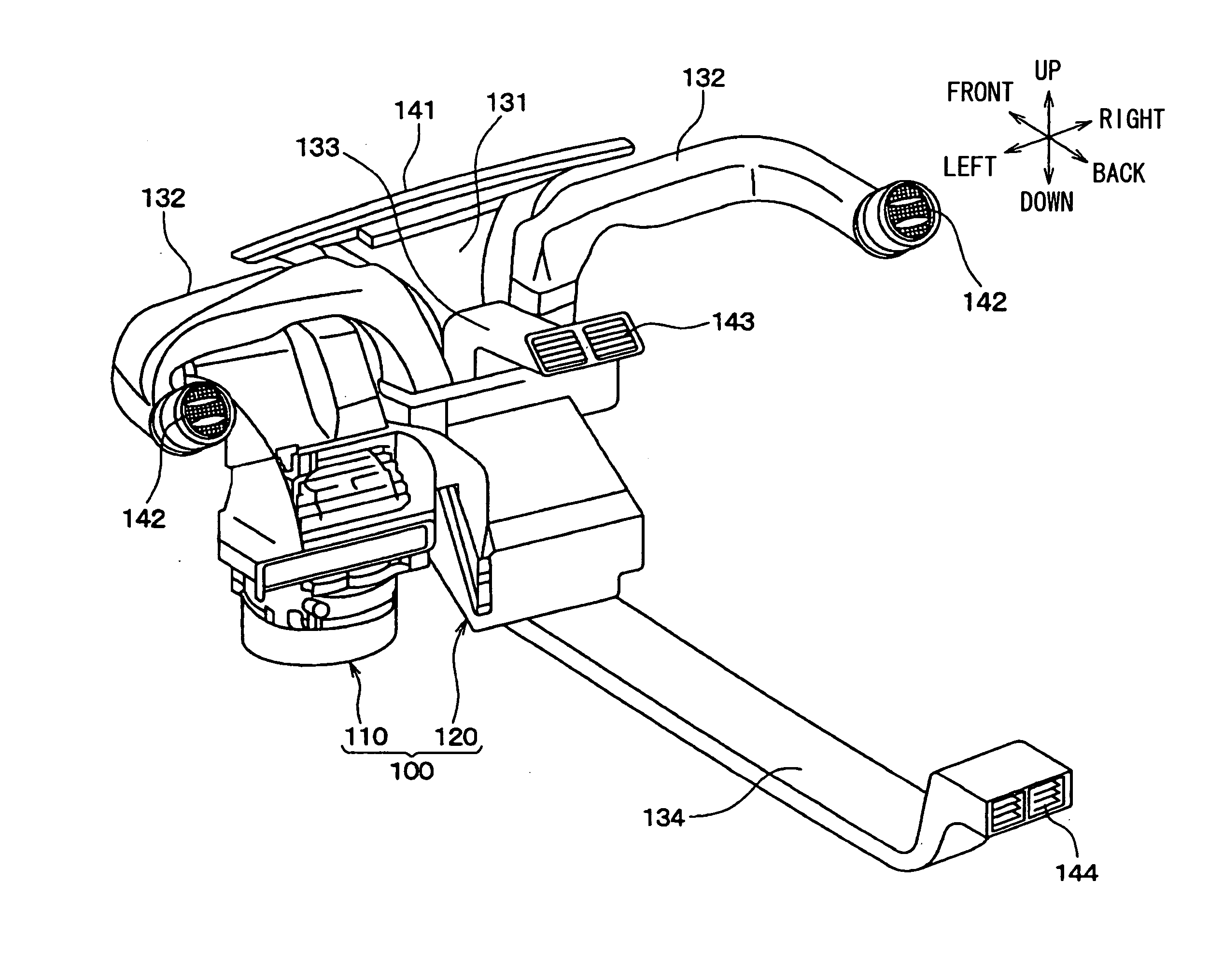
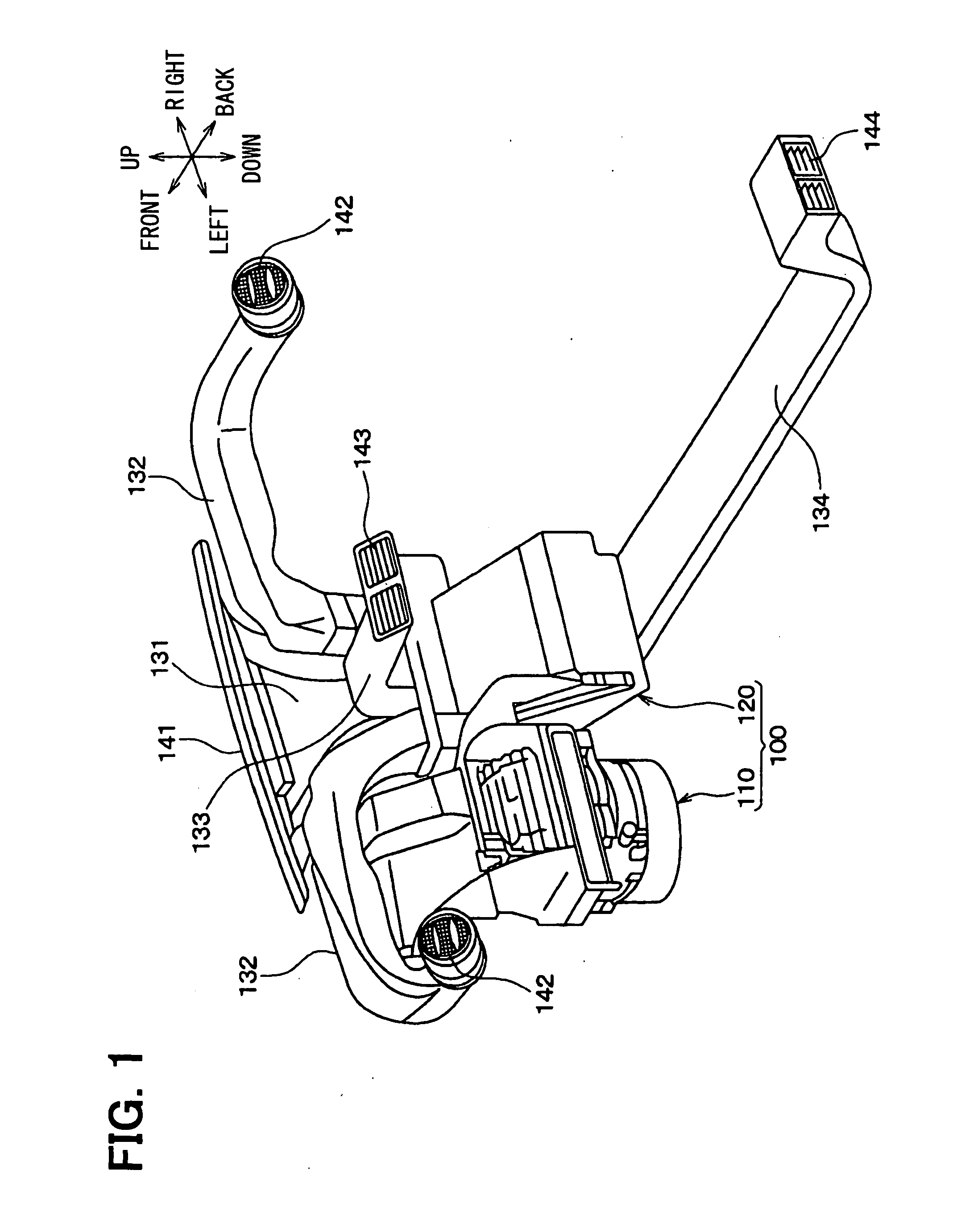
[0217] In this embodiment, the present invention is applied to a side face duct for a vehicle air conditioner. FIG. 22 is a partially-sectional view of the overall portion of a side face duct according to the eighth embodiment. FIG. 23 is a cross-sectional view taken along the line XXIII-XXIII of FIG. 22. In FIGS. 22 and 23, constituent elements identical to those of FIGS. 16 to 21 are designated by the same reference numerals as those of FIGS. 16 to 21.

[0218] As shown in FIG. 22, in the side face duct 132 of this embodiment, a passage dividing wall 2 is installed in the second bending section 3. Also, only a desired one of the outer-periphery-side inner wall surface 3a and the inner-periphery-side inner wall surface 3b of the second bending section 3, e.g., the outer-periphery-side inner wall surface 3a, is outwardly enlarged in this embodiment, as compared with the virtual line. For example, in this embodiment of FIG. 22, the outer-periphery-side inner wall surface 3a is bent app...

ninth embodiment

[0222] In this embodiment, the present invention is applied to a side face duct for a vehicle air conditioner. FIG. 24 is a partially-sectional view of the overall portion of a side face duct according to the ninth embodiment. FIG. 25 is a cross-sectional view taken along the line XXV-XXV of FIG. 24. In FIGS. 24 and 25, constituent elements identical to those of FIGS. 16 to 23 are designated by the same reference numerals as those of FIGS. 16 to 23.

[0223] As shown in FIG. 24, the side face duct 132 of this embodiment is shaped such that a first bending section 41, an upstream-side straight section 4, a second bending section 3, and a third bending section 42 constituting a duct section arranged downstream of the second bending section 3 are sequentially connected to one another. The side face duct 132 of this embodiment does not include the downstream-side straight section 5, different from the above-described embodiments.

[0224] In this embodiment, the length L7 of the retaining p...

tenth embodiment

[0226] In this embodiment, the present invention is applied to a side face duct for a vehicle air conditioner. FIG. 26 is a partially-sectional view of the overall portion of a side face duct according to the tenth embodiment. FIG. 27 is a cross-sectional view taken along the line XXVII-XXVII of FIG. 26. In FIGS. 26 and 27, constituent elements identical to those of FIGS. 16 to 25 are designated by the same reference numerals as those of FIGS. 16 to 25.

[0227] In this embodiment, the second bending section 3 is shaped such that the outer-periphery-side inner wall surface 3a is outwardly enlarged from a portion 45 arranged at an intermediate position in an air flow direction. Here, the portion 45 is located between the upstream-side straight section 4 and the second bending section 3.

[0228] In the second bending section 3, the outer-periphery-side air passage 6 is misaligned (offset) from the inner-periphery-side air passage 7 in a height direction by a height ΔH1.

[0229] Accordingl...


PUM


Abstract

An air duct for vehicle air conditioning, includes a duct body defining a passage, and a passage dividing wall for dividing an interior of the duct body into a first passage and a second passage. In the air duct, the width of the duct body in an arrangement direction of the first and second passages in a bending section is larger than the width of the duct body in upstream-side and downstream side straight sections adjacent to the bending section, so as to increase a passage length difference (L1−L2) between the first passage and the second passage. Accordingly, the air duct has a structure capable of reducing the duct width while obtaining a desired passage length difference between the first passage and the second passage.

Description

CROSS REFERENCE TO RELATED APPLICATION [0001] This application is based on Japanese Patent Applications No. 2006-214422 filed on Aug. 7, 2006, and No. 2007-163783 filed on Jun. 21, 2007, the contents of which are incorporated herein by reference in its entirety. FIELD OF THE INVENTION [0002] The present invention relates to an air duct for vehicle air conditioning, which guides conditioned air to an outlet port exposed to the interior of a vehicle compartment, and an air conditioner for a vehicle provided with such an air duct. BACKGROUND OF THE INVENTION [0003] A general air conditioner for a vehicle includes, for example, a compressor, a condenser, an evaporator, etc. constituting a refrigerant cycle. The vehicle air conditioner also includes an air conditioning body unit for air-conditioning a vehicle compartment, a blower unit including a blower, a vehicle air-conditioning air duct for guiding air from the air conditioning body unit to the vehicle compartment, and an outlet port...

Claims


Application Information

Patent Timeline
IPC IPC(8): B60H1/26B60H1/00
CPCB60H2001/006B60H1/00564B60H1/00028
Inventor KATOH, NAOKIHASHIMOTO, MINORUWATANABE, MASASHITOYAMA, TATSUYANAGAYA, SHIGEYOSHI
Owner DENSO CORP
Why Eureka
Try Eureka