Artificial mitral valve

a technology of mitral valve and artificial valve, which is applied in the field of cardiac surgery, can solve the problems of requiring artificial valve, affecting millions of people, and affecting the quality of life of mitral valve, and achieves the effect of reducing the risk of stenosis

Inactive Publication Date: 2008-02-07
GELBART DANIEL +1
View PDF24 Cites 162 Cited by
  • Summary
  • Abstract
  • Description
  • Claims
  • Application Information

AI Technical Summary

Benefits of technology

[0003]An artificial mitral valve is made of a short piece of elastomeric tubing having a one round end and one flattened end. The tubing can be rolled up to a small diameter and fits snuggly into the mitral valve opening when expanded. The tubing is attaches to a few rings made of thin flexible wire. When the rings are expanded inside the left atrium, they f

Problems solved by technology

Mitral valve degradation, such as regurgitation or stenosis, is a common problem affecting millions of people.
In initial stages the problem is caused by imperfect sealing of the leaflets.
Often those and other measure are insufficient and an artificial valve is required.
There are m

Method used


Image

  • Artificial mitral valve
  • Artificial mitral valve
  • Artificial mitral valve

Examples


Embodiment Construction

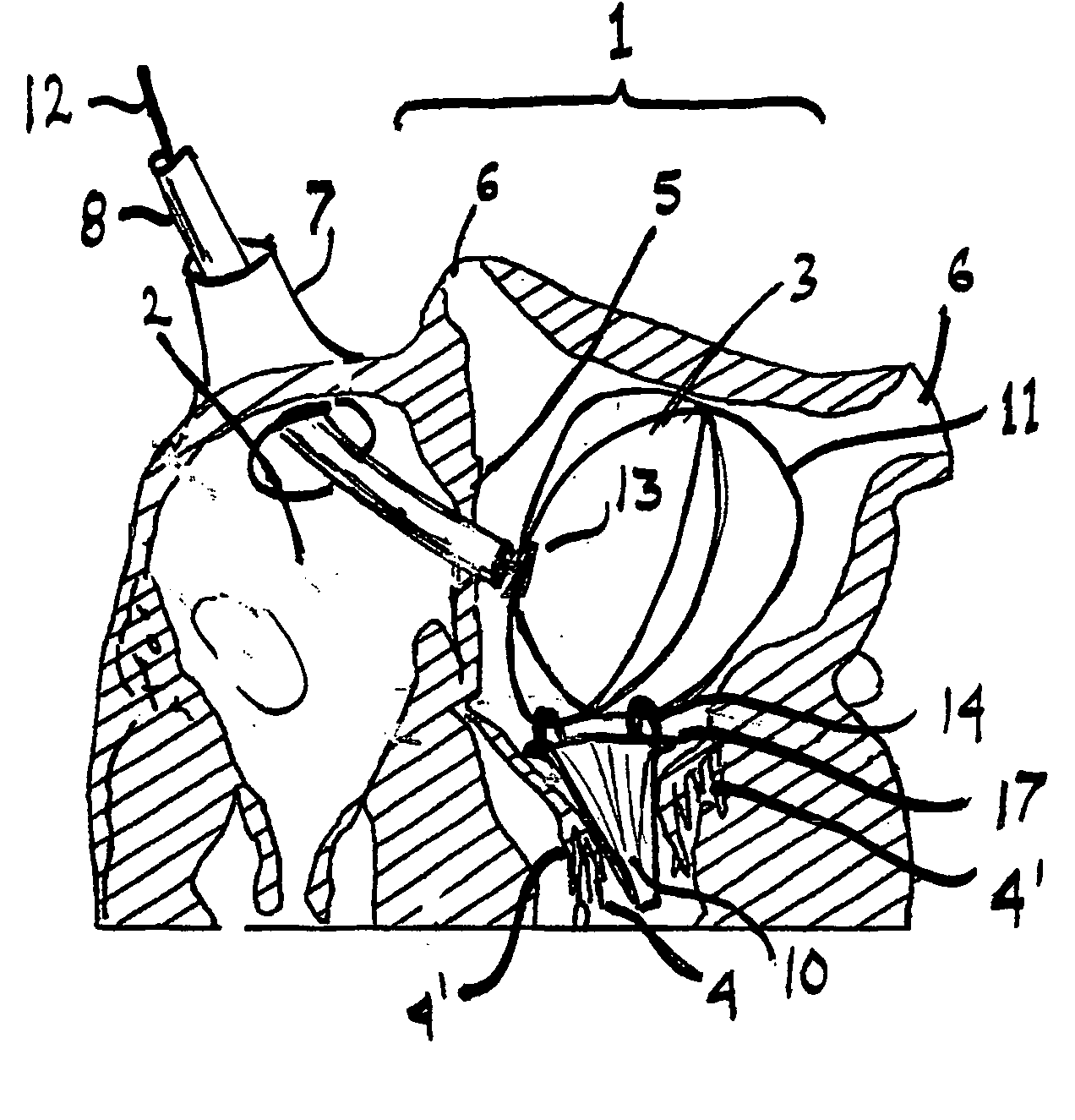
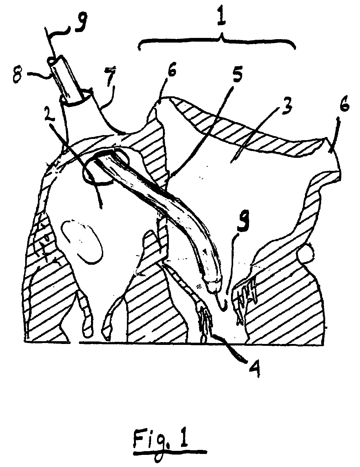
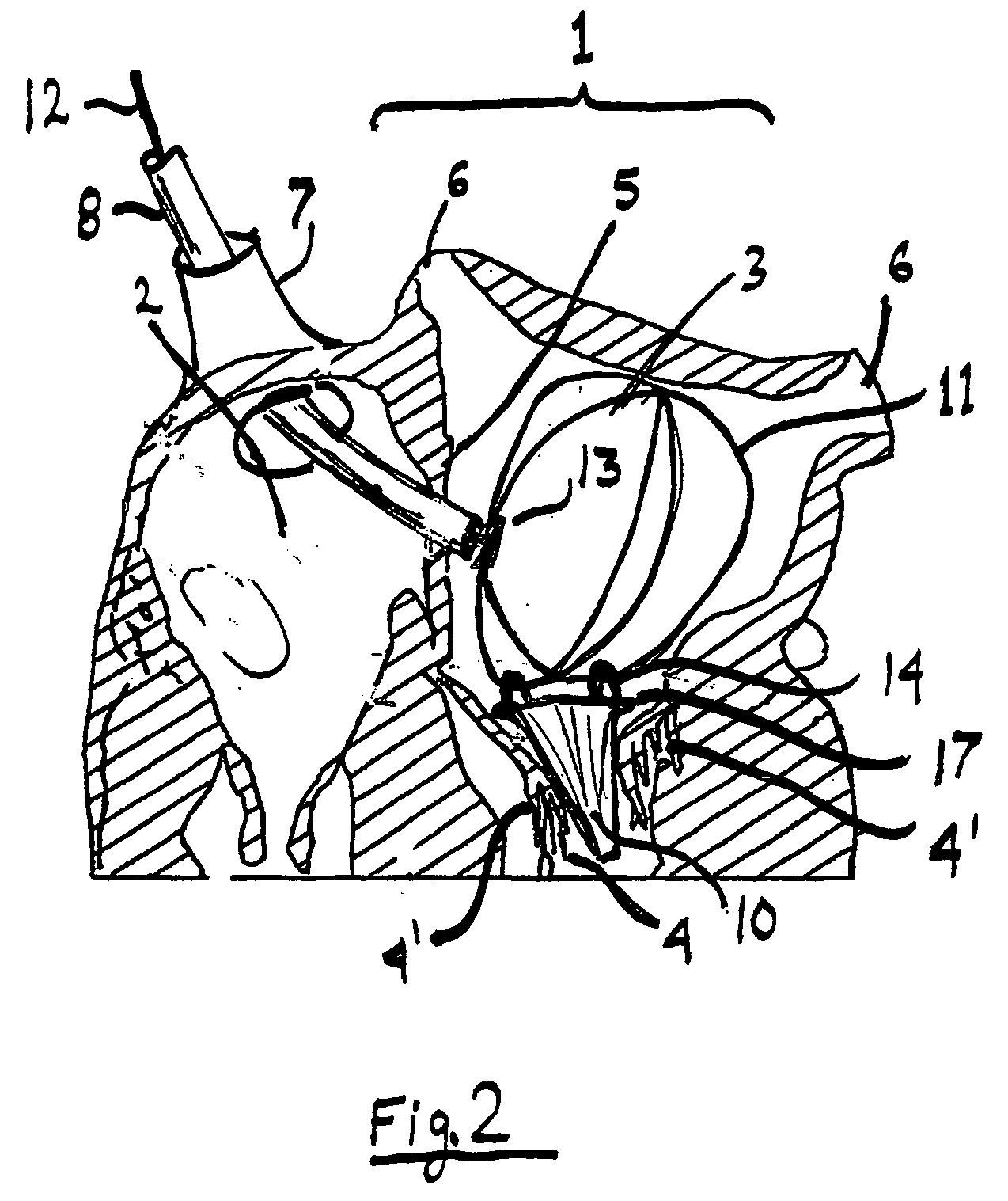
[0011]Referring now to FIG. 1, a catheter 9 is inserted into the left atrium 3 of heart 1 in order to reach defective mitral valve 4. Catheter 8 can be inserted through septum 5 via the vena cava 7 and right atrium 2, via the pulmonary veins 6 or by using any of the methods known in the art for minimally invasive or percutaneous cardiac surgery. Typically catheter 8 is guided by guide wire 9. The art of inserting catheters into the mitral valve is well known. Once tip of catheter 8 reaches mitral valve 4 the artificial valve is pushed out and catheter is retracted as shown in FIG. 2.

[0012]Referring now to FIG. 2, the flexible artificial valve 10 fits snuggly in the opening of mitral valve 4. Mitral valve leaflets 4′ help with forming a hemostatic seal as ventricular blood pressure pushes them against artificial valve 10. Even if leaflets 4′ separate from valve 10 during diastolic phase the form a secondary valve around artificial valve 10. Expanded wire rings 11 are supported by the...


PUM


Abstract

An artificial mitral valve is made of a short piece of elastomeric tubing having a one round end and one flattened end. The tubing can be rolled up to a small diameter and fits snuggly into the mitral valve opening when expanded. The tubing attaches to a few rings made of thin flexible wire. When the rings are expanded inside the left atrium, they form a support structure holding the artificial valve in the correct position. The rings can be flattened and delivered via a catheter together with the valve. The artificial valve contains no rigid component, therefore it does not deform or damage the area around the defective mitral valve and can be installed even in highly calcified or deteriorated valves.

Description

FIELD OF THE INVENTION [0001]The invention relates to cardiac surgery, and in particular to percutaneous replacement of the mitral valveBACKGROUND OF THE INVENTION [0002]Mitral valve degradation, such as regurgitation or stenosis, is a common problem affecting millions of people. In initial stages the problem is caused by imperfect sealing of the leaflets. This can be remedied by deforming the valve annulus to bring leaflet closer together, for better contact, or installing a device between the two leaflets in order to reduce the distance each leaflets needs to cover. Often those and other measure are insufficient and an artificial valve is required. There are many designs of prior art valves but a common problem is the anchoring of the artificial valve in a percutaneous procedure, where anchoring by suturing is not practical. U.S. patent application 2006 / 0058871 discloses a novel way of anchoring a pocket to reduce the distance between the valve leaflets. It was found that a simila...

Claims


Application Information

Patent Timeline
IPC IPC(8): A61F2/24
CPCA61F2/2412A61F2/246A61F2/2436A61F2/2418
Inventor GELBART, DANIELLICHTENSTEIN, SAMUEL VICTOR
Owner GELBART DANIEL
Why Eureka
Try Eureka