Method and system for controlling heating ventilation and air conditioning (HVAC) units

a technology for heating ventilation and air conditioning, applied in the direction of electric controllers, heating types, instruments, etc., can solve the problems of large temperature differentials, inadequate and/or inappropriate cooling for different locations in the building, and thermostat placement, etc., and achieve the effect of avoiding the need for wire runs

Inactive Publication Date: 2008-02-07
INNOVATION BY DESIGN
View PDF16 Cites 66 Cited by
  • Summary
  • Abstract
  • Description
  • Claims
  • Application Information

AI Technical Summary

Benefits of technology

[0004]The present invention provides an HVAC control method and system including a central controller that controls energy storage unit operated registers / vents. Each register / vent captures energy of air flowing in the duct system and converts to an electrical current that is stored locally in a energy storage unit in the register / vent. Further, wireless communication between the central controller and the register / vents alleviates the need for wire runs and professional installation. Use of unique register identifiers allows the central controller to individually control each register based on user settings. As such, the user can install one or more registers and individually control one or more registers for desired temperature control in each zone. Preferably, the user can control each register for desired temperature control in a zone.

Problems solved by technology

However, various rooms in a building, and especially those on different floors, may have large temperature differentials.
Therefore, it is common that a thermostat placed in a room of one floor cannot detect increasing heat accumulating in another area or floor in the building.
This leads to inadequate and / or inappropriate cooling for different locations in the building.
Additionally, such units are not energy efficient and lack user control.
However, such zoning devices are complex, expensive and very labor intensive to install properly.
Further, such systems do not allow the ability to monitor heating and cooling requirements via graphical user interfaces locally or remotely such as Internet-based (e.g., Web-based) interfaces.

Method used


Image

  • Method and system for controlling heating ventilation and air conditioning (HVAC) units
  • Method and system for controlling heating ventilation and air conditioning (HVAC) units
  • Method and system for controlling heating ventilation and air conditioning (HVAC) units

Examples


Embodiment Construction

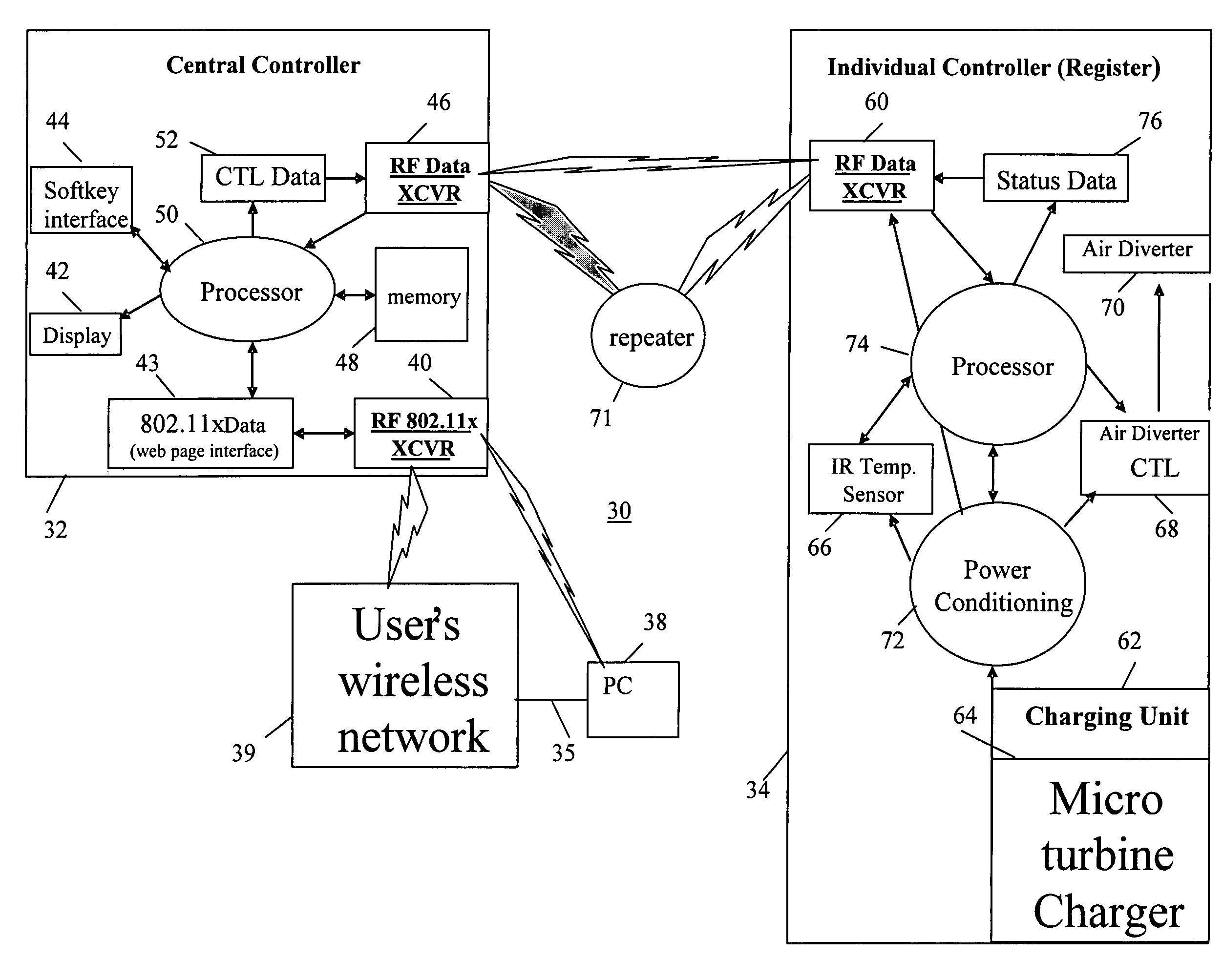
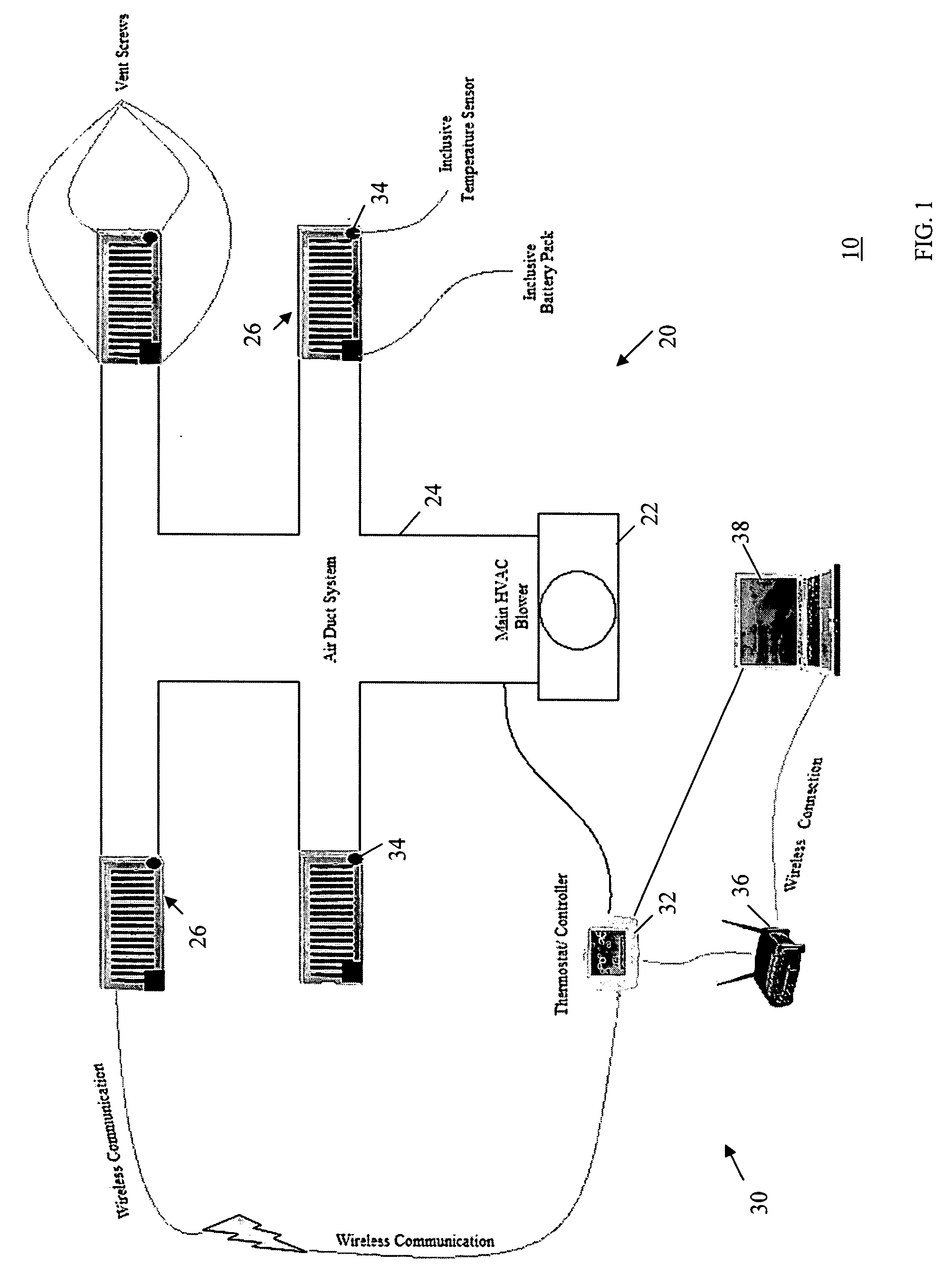
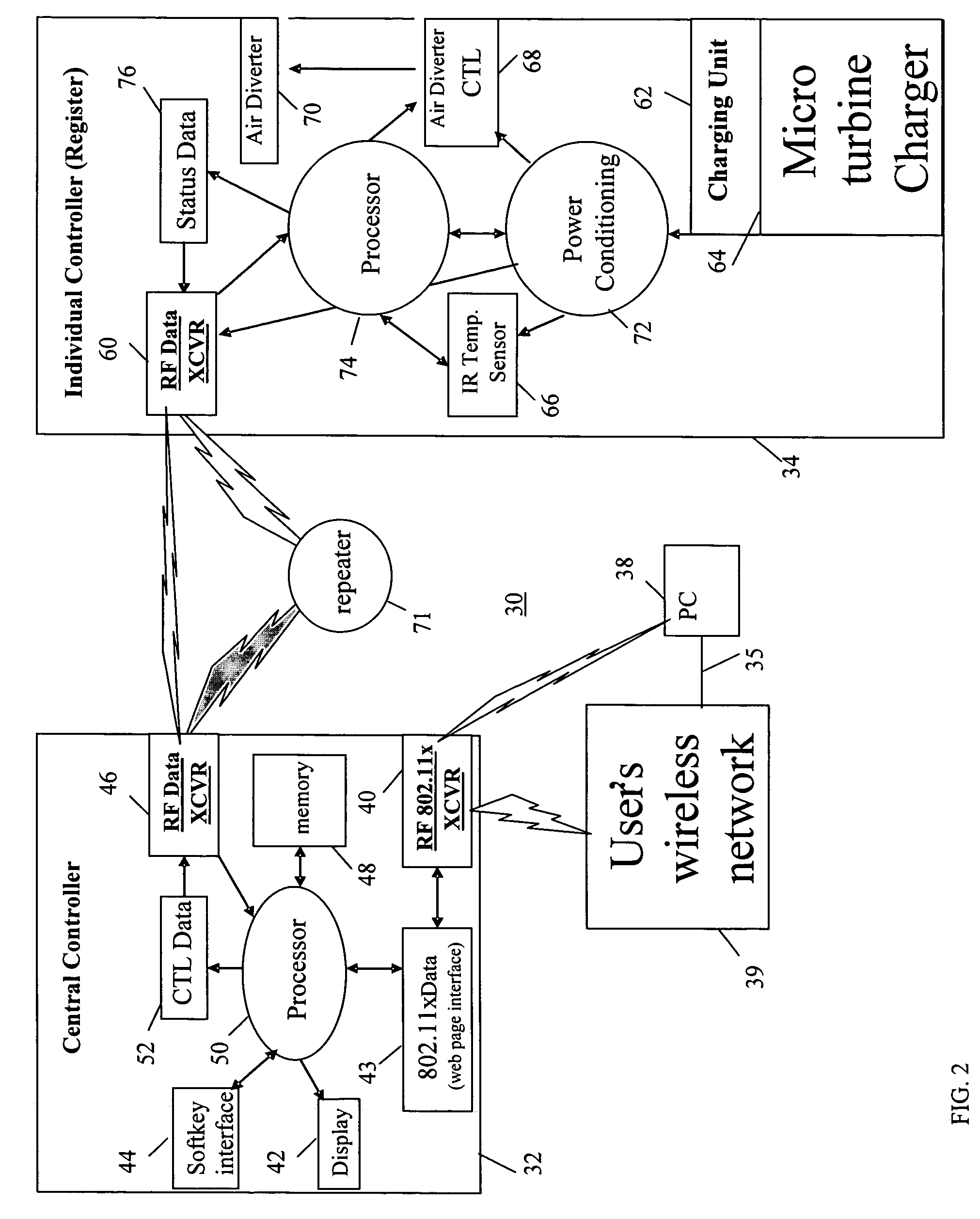
[0030]The present invention provides preferred methods and apparatuses for control of HVAC units. In one preferred embodiment, the present invention utilizes wireless communication technology for communicating between a control system with a central temperature controller, and distributed individual vent controllers for automated vents of an HVAC unit. FIG. 1 shows a block diagram of an HVAC system 10 including an HVAC unit 20 and a wireless control system 30, implementing a method of controlling the HVAC unit 20, according to a preferred embodiment of the present invention.

[0031]The HVAC unit 20 includes a blower 22 and air ducts 24 which deliver forced air from the blower 22 to multiple air vents 26. The control system 30 includes a central controller 32 that communicates with individual vent controllers 34 via wireless communication (e.g., X10 wireless transceiver). In this example, the individual vent controllers 34 are shown connected to the vents 26.

[0032]Preferably, the contr...


PUM


Abstract

An HVAC control system provides a central controller that controls registers/vents which capture energy of air flowing in the duct system and convert it to an electrical current that is stored locally in energy storage units in the register/vent. Further, wireless communication between the central controller and the register/vents alleviates the need for wire runs and maintenance. Use of unique register identifiers allows the central controller to individually control each register based on user settings. As such, the user can install one or more registers and individually control one or more registers for desired temperature control in each zone. A wireless network allows user interaction with the central controller via a Web-page utilizing a Web browser on a PC that wirelessly connects to the central controller (e.g., via a wireless network). The register/vent combination is preferably and all-in-one unit that slides into the air duct opening in each zone.

Description

FIELD OF THE INVENTION [0001]The present invention relates to HVAC control mechanisms; and in particular to an interactive group of functions that allow a user to interact with and control HVAC unit.BACKGROUND OF THE INVENTION [0002]HVAC units are utilized in various capacities for the heating and cooling of areas inside the buildings. The standard for conventional HVAC units is to place a thermostat in one of the rooms within the building. The thermostat determines the room temperature at its physical location and determines whether the room temperature is below or above a user's requirements. However, various rooms in a building, and especially those on different floors, may have large temperature differentials. Therefore, it is common that a thermostat placed in a room of one floor cannot detect increasing heat accumulating in another area or floor in the building. The reverse is also common. This leads to inadequate and / or inappropriate cooling for different locations in the bui...

Claims


Application Information

Patent Timeline
Patent Type & Authority Applications(United States)
IPC IPC(8): G01M1/38G05B13/00G05B11/01
CPCF24F11/006F24F2011/0071F24F2011/0068F24F11/30F24F11/62F24F11/56F24F11/58F24F11/52
Inventor AMINPOUR, ROUZBEHGADDIS, MARC
Owner INNOVATION BY DESIGN
Why Eureka
Try Eureka