Apparatus for spraying etchant and use method thereof

a technology of etchant and apparatus, which is applied in the manufacture of printed circuits, cable/conductor manufacture, printed circuits, etc., can solve the problems of puddle effect, chemical etching also suffers from a problem, etc., and achieve the effect of increasing the spray pressur

Active Publication Date: 2008-02-14
GARUDA TECH CO LTD
View PDF2 Cites 11 Cited by
  • Summary
  • Abstract
  • Description
  • Claims
  • Application Information

AI Technical Summary

Benefits of technology

[0009]In one embodiment, an apparatus for spraying an etchant includes a manifold, a plurality of feed pipes in fluid communication with the manifold, each of the feed pipes having a number of spray nozzles mounted thereon, the feed pipes cooperatively constitute a spray region, and a pressure-boosting device configured for increasing a spray pressure of the spray nozzles which are located in a central area of the spray region.

Problems solved by technology

However, chemical etching also suffers from a problem known as “the puddle effect”.

Method used


Image

  • Apparatus for spraying etchant and use method thereof
  • Apparatus for spraying etchant and use method thereof
  • Apparatus for spraying etchant and use method thereof

Examples


first embodiment

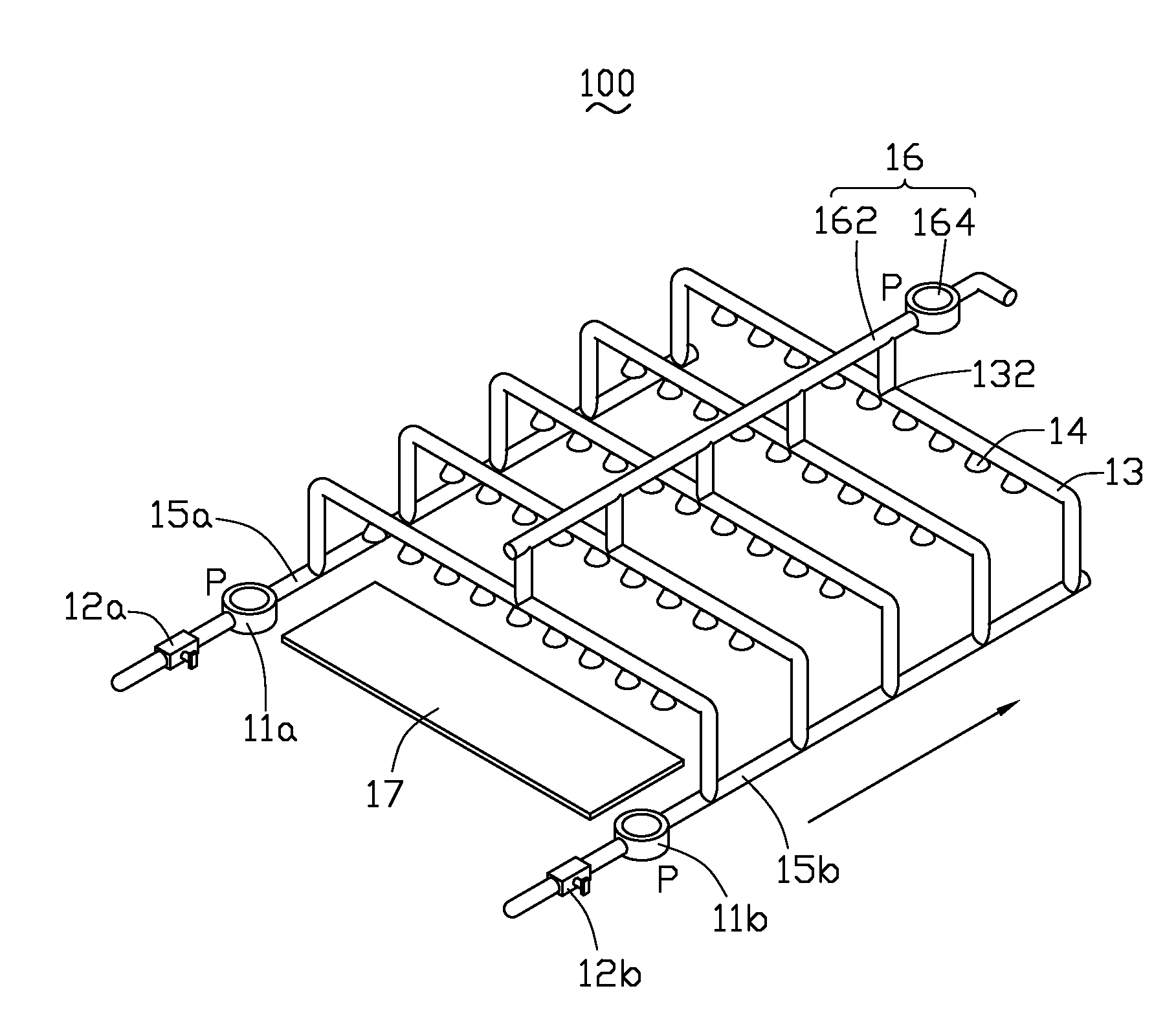
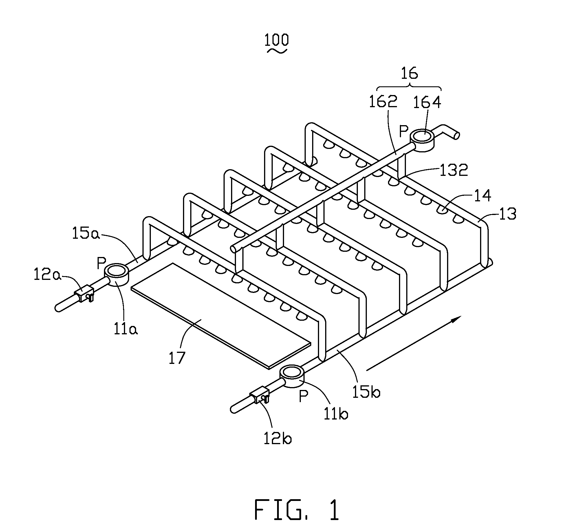
[0016]Referring to FIG. 1, an apparatus 100 for spraying etchant in accordance with a first embodiment includes pumps 11a, 11b, valves 12a, 12b, manifolds 15a, 15b, a number of feed pipes 13 and a pressure-boosting device 16. The pump 11a and the valve 12a are mounted on the manifold 15a. The pump 11b and the valve 15b are mounted on the manifold 15b. The valves 12a, 12b are used for regulating a flow of etchant in the manifolds 15a, 15b respectively. The feed pipes 13 are arranged parallel to each other and spaced an equal interval from each other. Two ends of each of the feed pipes 13 are in fluid communication with the manifolds 15a, 15b respectively. Each of the feed pipes 13 is provided with a number of spray nozzles 14 for spraying. In the preferred embodiment, the pressure-boosting device 16 includes a pressure-boosting pipe 162 and a pump 164 mounted on the pressure-boosting pipe 162. The pressure-boosting pipe 162 is in fluid communication with each of the feed pipes 13 at ...

second embodiment

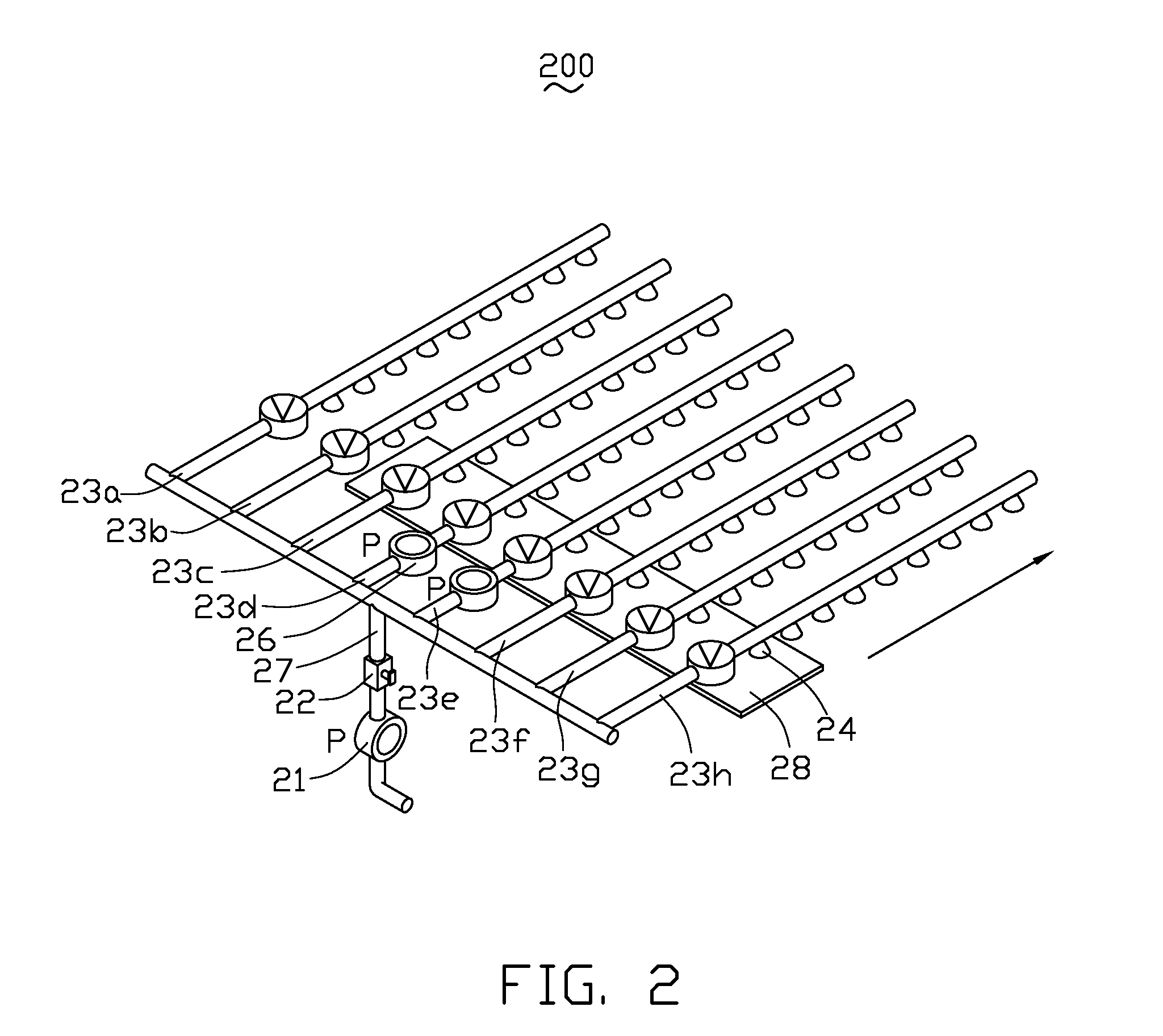
[0020]Referring to FIG. 2, an apparatus 200 for spraying an etchant in accordance with the second embodiment includes a pump 21, a valve 22 and feed pipes 23a, 23b, 23c, 23d, 23e, 23f, 23g, 23h. The pump 21 supplies etchant to each of the feed pipes through a manifold 27. The feed pipes 23a, 23b, 23c, 23d, 23e, 23f, 23g, 23h are disposed at equal intervals. A mass flow controller (MFC) 25 is mounted on each of the feed pipes 23a, 23b, 23c, 23d, 23e, 23f, 23g, 23h. A pressure-boosting pump 26 is mounted on each of the feed pipes 23d, 23e. The pressure-boosting pump 26 is configured for improving a spray pressure in the feed pipes 23d, 23e.

[0021]When a printed circuit board 28 is etched with the apparatus 200, the printed circuit board 28 conveyed by a feed roller (not shown) at a direction that is parallel to the feed pipes or at a certain angle with the feed pipes. Because the spray pressure in the feed pipes 23d, 23e is higher than that in the feed pipes 23a, 23b, 23c, 23f, 23g, 2...


PUM

PropertyMeasurementUnit
pressureaaaaaaaaaa
spray pressureaaaaaaaaaa
circuit densityaaaaaaaaaa

Abstract

The present invention relates to an apparatus for spraying an etchant and a method for manufacturing a printed circuit board. In one exemplary embodiment the apparatus includes a manifold, a plurality of feed pipes in fluid communication with the manifold, each of the feed pipes having a plurality of spray nozzles mounted thereon, the feed pipes cooperatively constitute a spray region, and a pressure-boosting device configured for increasing a spray pressure of the spray nozzles which are located at a central area of the spray region. The apparatus can overcome “the puddle effect” on an upper surface of the printed circuit board.

Description

BACKGROUND[0001]1. Technical Field[0002]The present invention relates to an apparatus for spraying an etchant and a method for using such an apparatus to etch a printed circuit board.[0003]2. Discussion of Related Art[0004]Recently, as the electronic appliances are becoming smaller in size and diversified in function, printed circuit boards (PCBs) widely used in such electronic appliances are required to have higher circuit density and reliability.[0005]Usually, a chemical etching process is used for etching a conductive pattern on a copper clad laminate (CCL) as described below. First, a photoresist layer is applied on the CCL by screen printing method. Second, the CCL is driven to pass through an etching bath by a feed roller, thereby an etchant is sprayed simultaneously and evenly onto both an upper surface and a bottom surface of the CCL by a number of spray nozzles. As a result, the copper layer uncovered by the photoresist layer is etched and a conductive pattern is formed on ...

Claims


Application Information

Patent Timeline
Patent Type & Authority Applications(United States)
IPC IPC(8): H01B13/00B44C1/22C23F1/00
CPCC23F1/08H05K2203/075H05K3/068
Inventor LEE, WEN-CHINLIN, CHENG-HSIEN
Owner GARUDA TECH CO LTD
Why Eureka
Try Eureka