Method for the Transmission of Electrical Pneumatic or Hydraulic Energy and an Energy Transmission System

Active Publication Date: 2008-02-14
JOST WERKE
View PDF35 Cites 11 Cited by
  • Summary
  • Abstract
  • Description
  • Claims
  • Application Information

AI Technical Summary

Benefits of technology

[0014] The setting signal can be transmitted wirelessly or by wires via the plug-in coupling system. The transmission is also dependent on whether the plug-in coupling system is supposed to be connected permanently or temporarily. In the latter case, if the energy storage device is sufficiently full,

Problems solved by technology

If, however, a leak occurs, it is always possible to continue operating the consuming unit from the energy storage

Method used


Image

  • Method for the Transmission of Electrical Pneumatic or Hydraulic Energy and an Energy Transmission System
  • Method for the Transmission of Electrical Pneumatic or Hydraulic Energy and an Energy Transmission System
  • Method for the Transmission of Electrical Pneumatic or Hydraulic Energy and an Energy Transmission System

Examples


Embodiment Construction

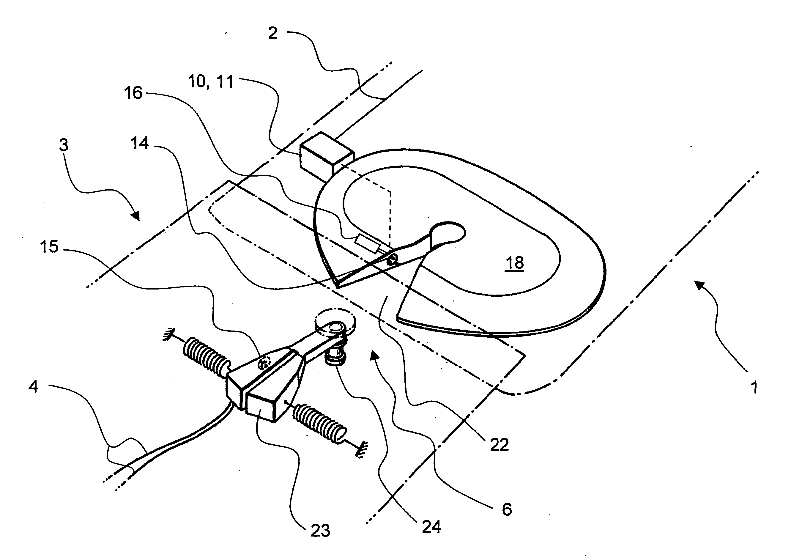
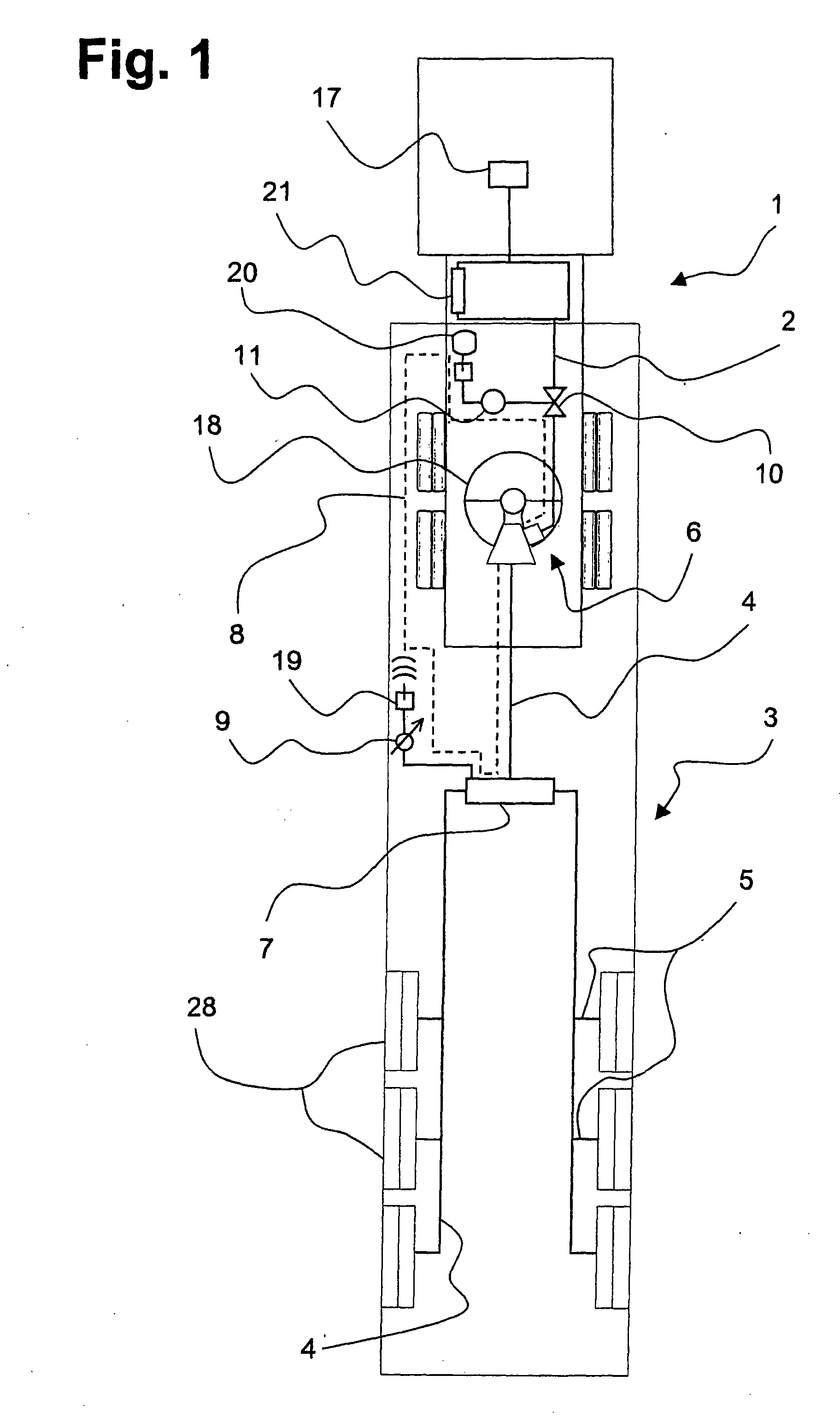
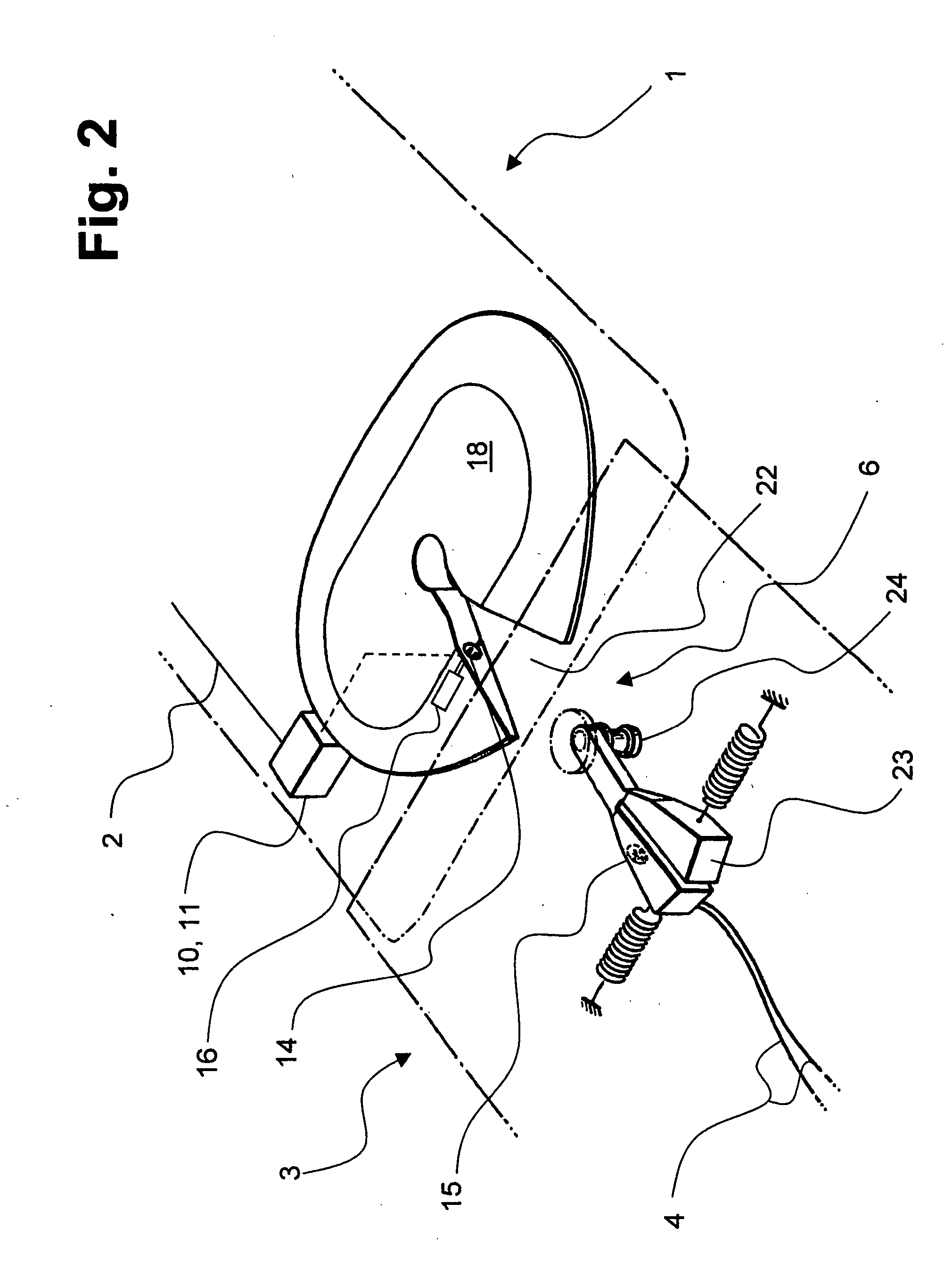
[0031]FIG. 1 shows in a schematic top view a tractor trailer rig, comprising a tractor as the first vehicle 1 and a semitrailer as the second vehicle 3, coupled to the first vehicle 1 in familiar fashion by means of a fifth wheel 18.

[0032] On the first vehicle 1 is situated an energy supply trunk 2 and on the second vehicle 3 an energy distribution trunk 4, which together form the energy transmission system of the invention and are designed, for example, to furnish pressurized air. An energy transmission system to furnish electrical energy would be constructed similarly, but with different components familiar to the practitioner.

[0033] The energy supply trunk 2 is fed by a compressor 17 with pressurized air and supplies pressurized air to consumers of the first vehicle 1 in a circuit, not further shown. These consumers of the first vehicle include, for example, the pressurized brake system. The energy supply trunk 2 has a pressurized tank 21 to balance out the peak loads.

[0034] T...


PUM


Abstract

A method for the transmission of electrical, pneumatic, or hydraulic energy between a first vehicle and a second vehicle, coupled thereto, for example a tractor vehicle and a trailer and an energy transmission system. The aim of the invention is development of a method and an energy transmission system permitting an operationally-secure driving condition over a long period even with a partly or completely damaged plug coupling system. Said aim is achieved by means of, amongst other things, a method whereby the energy in the energy distribution line is introduced from the energy supply line in a controlled manner.

Description

FIELD OF THE INVENTION [0001] The invention concerns a method for transmitting of electric, pneumatic or hydraulic energy between a first vehicle and a second vehicle coupled to the former, for example, a tractor and a semitrailer. The invention is also implemented in an energy transmission system. BACKGROUND OF THE INVENTION [0002] Normally, the first and second vehicle are at first joined together mechanically via a coupling. By coupling is meant, for example, a fifth wheel, into which a king pin arranged at the trailer side is introduced via a wedgelike tapering entry opening and can be locked together with the fifth wheel. In older vehicles, the fixed supply lines installed on the first vehicle are then connected by the driver by hand to the second vehicle, making use of plug-in couplings. The supply lines include both pressurized air lines and current conducting cables, sometimes also hydraulic lines, and they are provided with energy from an energy supply trunk of the first ve...

Claims


Application Information

Patent Timeline
IPC IPC(8): B62D53/12
CPCB60D1/62B62D53/125B60T17/043
Inventor ALGUERA, JOSE
Owner JOST WERKE
Why Eureka
Try Eureka