Wheel Shock Absorbing Apparatus

a technology of shock absorption apparatus and wheel, which is applied in the direction of suspensions, hubs, vehicle components, etc., to achieve the effects of compact design, improved travel ratio, and light weigh

Inactive Publication Date: 2008-02-14
LUND MORTEN A
View PDF21 Cites 7 Cited by
  • Summary
  • Abstract
  • Description
  • Claims
  • Application Information

AI Technical Summary

Benefits of technology

[0029] An aspect of the present invention may then be generally described as an improved wheel suspension system where the major suspension parts are arranged in such a manner that the axle moves within the hub of the wheel. One advantage is an improved ratio of travel resulting from moving the springing element from under the axle as in many prior art devices to a cavity or space in the outer end cap. Other advantages of this development are lighter weight, compact design, and a geometry which gives a better motion of the wheel relative to the vehicle. In particular, this suspension system provides an efficient and lightweight means of absorbing vibration and minor irregularities in the travel surface.
[0030] A further aspect of the present invention may be generally described as an improved wheel suspension system where the major suspension parts are arranged in such a manner that the axle moves in an arc around a shaft with a rigidly attached paddle. A springing element is seated in a cavity formed within a module defined by respective outer end caps in such a manner that the paddle acts progressively on the springing element as the axle moves through an arc. The shaft with paddle passes through the module and is rigidly attached to the frame of the vehicle. The dimensions and placement of the paddle control and restrain the lateral position of the module relative to the vehicle. Among the advantages to this development are light weight, compact sealed design, spring adjustability, and low cost of manufacturing. The suspension system may be applied to any implement or vehicle that requires suspension. In particular, this suspension system provides an efficient and light-weight means of absorbing vibration and minor irregularities in the travel surface.
[0031] A still further aspect of the present invention may be generally described as a center tube on which a wheel hub is mounted having a C-pocket through hole cooperative with a tubular springing element positioned about the axle to provide a desired amount of damping, or drag, against the sides of the C-pocket through hole as the axle moves in an arc relative to a pivot stud. The amount of such damping may be varied at will by selection of elastomer parts of differing size and shape and density. The shape and dimensions of the C-pocket determine the amount of compression and deformation exerted on the axle, and any enclosed elastomers, by the movement of the axle, and the length and thickness of the elastomer ring fitted to the axle determines the amount of damping applied to the movement of the axle; that is, a “shock-absorber” type of reaction is achieved through this aspect of the present invention whereby the speed of the return movement of the axle is controlled and limited for the sake of comfort and vehicle control.

Problems solved by technology

The prior art described above teaches various wheel suspension hubs and devices, but does not teach a wheel shock absorbing apparatus providing further advantages in shock absorption and travel by improving the geometry and mechanical interaction of the components and effectively moving the suspension elements out of the wheel hub itself.

Method used


Image

  • Wheel Shock Absorbing Apparatus
  • Wheel Shock Absorbing Apparatus
  • Wheel Shock Absorbing Apparatus

Examples


Embodiment Construction

[0046] The above described drawing figures illustrate aspects of the invention in at least one of its exemplary embodiments, which are further defined in detail in the following modes.

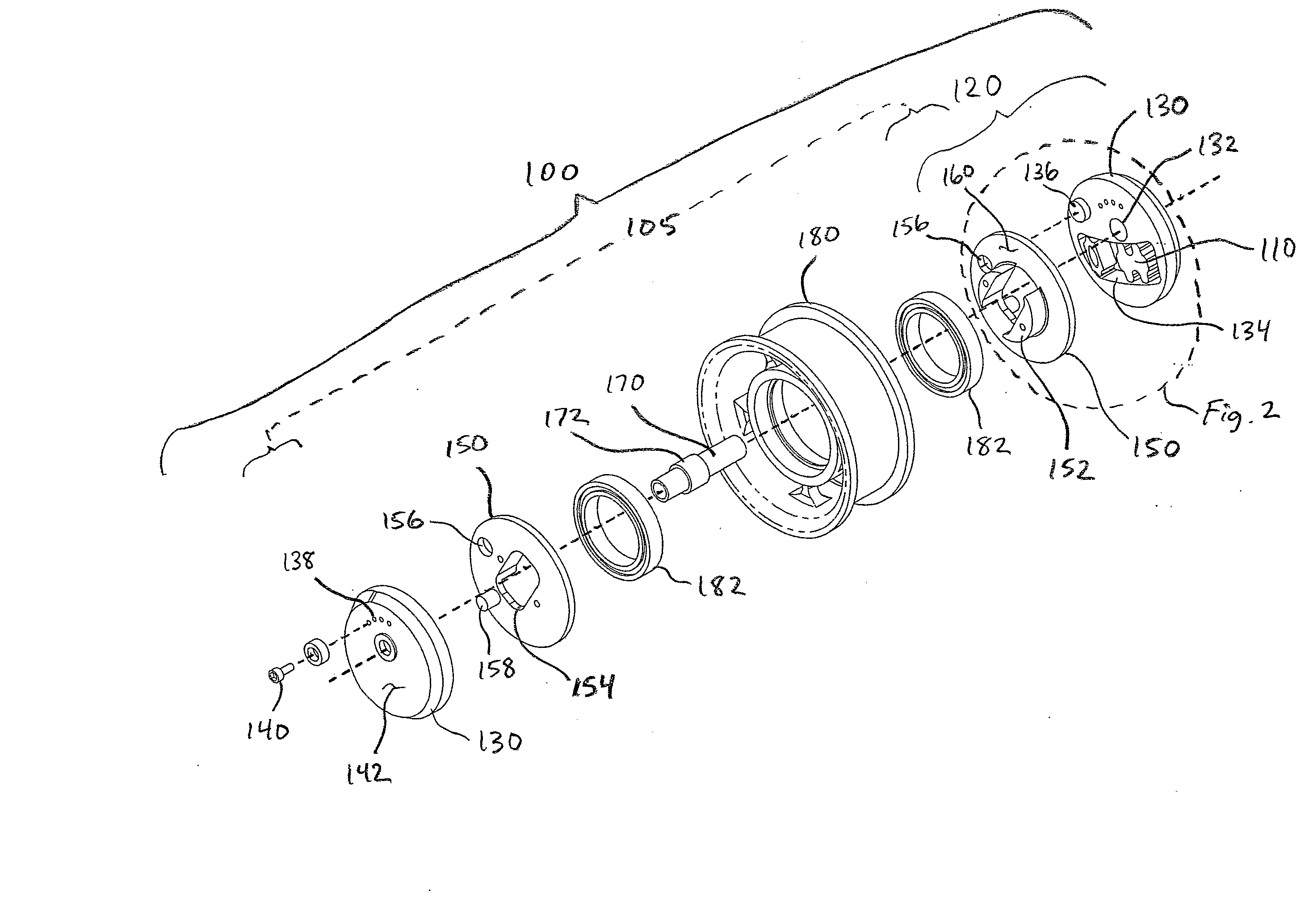
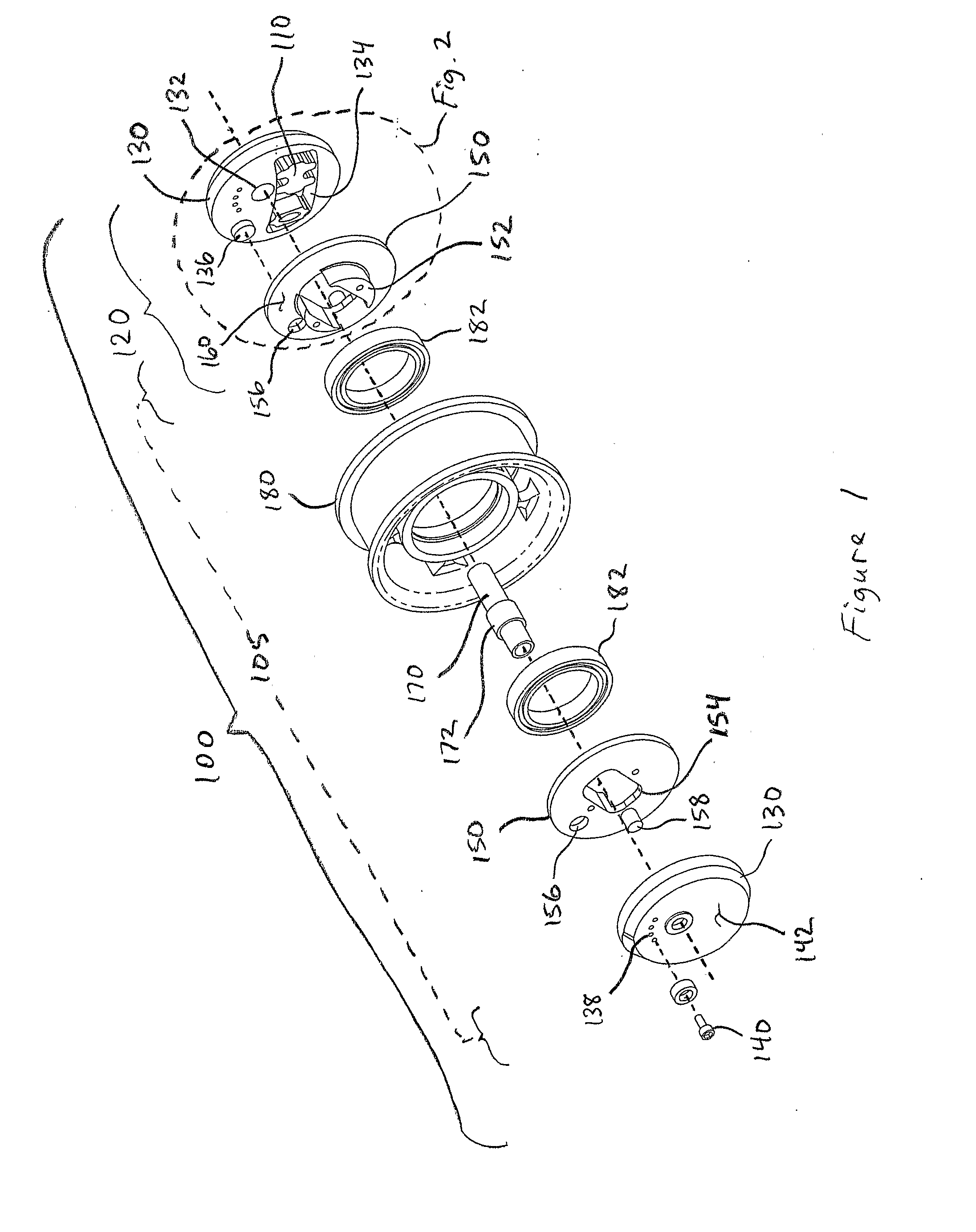
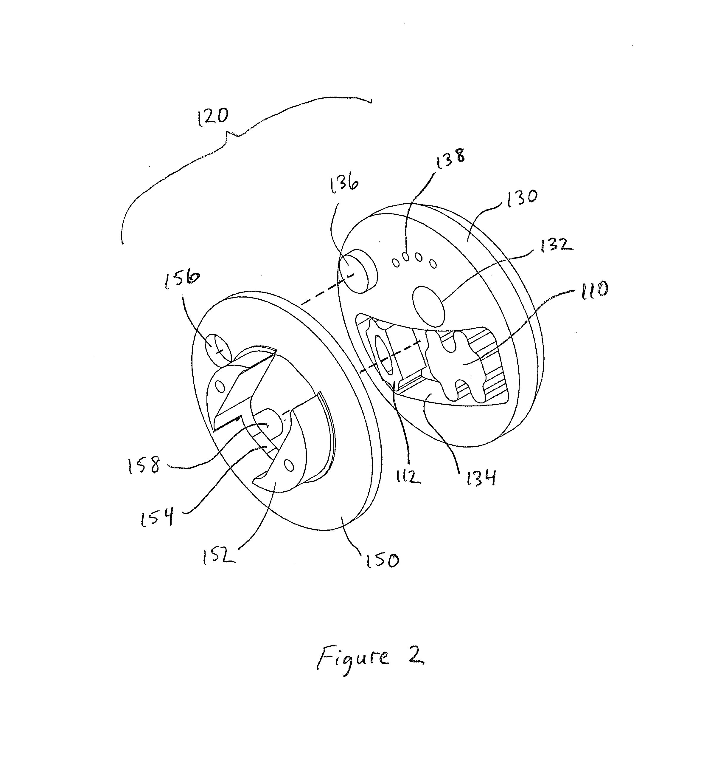
[0047] A first exemplary embodiment of the wheel shock absorbing apparatus of the present invention as shown in FIGS. 1 and 2 is an assembly 100 made up in part of a springing element 110, normally a coiled spring or an elastomer, seated within a divided end cap 120 in such a manner that the springing action occurs when the parts of the divided end cap pivot relative to one another, one side of the pivot effectively acting against the axle 170, and the other side of the pivot effectively acting against the hub 180, with the seated springing element 110 limiting the pivot action in such manner as to control the velocity and extent of the travel allowed to the axle 170 through its arc of motion relative to the hub as delimited by its effective pivot about the pivot stud 136 of the outer end cap 130, mor...


PUM


Abstract

A wheel shock absorbing apparatus includes: a hub, one or more bearings seated within the hub, and an axle. At least two outer end caps, each with an axle mounting hole and an offset inwardly opening cavity, enclose the ends of the hub. A springing element is positioned within each cavity in the end caps, and an inner body unit is located between the outer end caps. An actuation stud projects from the inner body unit into the cavities to contact the springing element. Fastening elements secure the outer end caps together on opposite side of the inner body unit. A pivot stud allows the respective outer end caps and inner body unit to pivot with respect to one another, which causes the actuation stud to contact the spring element, which absorbs shocks as the wheel travels over a surface during locomotion of a vehicle.

Description

RELATED APPLICATIONS [0001] This application claims priority and is entitled to the filing date of U.S. Provisional application Ser. No. 60 / 570,008 filed May 10, 2004, and entitled “Internal Suspension Hub with a C-Pocket Center Tube,” U.S. Provisional application Ser. No. 60 / 582,281 filed Jun. 23, 2004, and entitled “Internal Suspension Hub with an Expanded C-Pocket Center Tube,” U.S. Provisional application Ser. No. 60 / 631,119 filed Nov. 24, 2004, and entitled “Internal Shock Absorbing Hub,” and U.S. Provisional application Ser. No. 60 / 645,522 filed Jan. 18, 2005, and entitled “internal Shock Absorbing Module.” The contents of the aforementioned applications are incorporated herein by reference.INCORPORATION BY REFERENCE [0002] Applicant hereby incorporates herein by reference any and all U.S. patents and U.S. patent applications cited or referred to in this application. TECHNICAL FIELD [0003] Aspects of this invention relate generally to shock absorbing systems for vehicles, and ...

Claims


Application Information

Patent Timeline
Patent Type & Authority Applications(United States)
IPC IPC(8): B60B27/00B60G11/00B60B9/00
CPCB60B9/005
Inventor LUND, MORTEN A.
Owner LUND MORTEN A
Why Eureka
Try Eureka