High efficiency linear motor and oil well lift device

a linear motor and high efficiency technology, applied in the direction of dynamo-electric components, propulsion systems, borehole/well accessories, etc., can solve the problems of low energy efficiency of linear-motor powered oil well surface units for sucker rod actuation, low energy efficiency of tubular linear motors in high relative thrust/low speed mode, etc., to achieve high energy efficiency and low cost

Inactive Publication Date: 2008-02-14
RAOS DAVOR JACK
View PDF5 Cites 22 Cited by
  • Summary
  • Abstract
  • Description
  • Claims
  • Application Information

AI Technical Summary

Benefits of technology

[0006]The present invention is an electric linear motor optimized for applications such as oil well pumping where high energy efficiency i...

Problems solved by technology

Other prior art linear motors have a closed tubular mechanical configuration that is not optimum for attaching and interfacing to external equipment such as bearings, loads and counterbalances.
Tubular linear motors are also limited in terms of energy efficiency in a high relative thrust/low speed mode.
Prior art linear-motor powered oil well surface units for sucker rod actuati...

Method used


Image

  • High efficiency linear motor and oil well lift device
  • High efficiency linear motor and oil well lift device
  • High efficiency linear motor and oil well lift device

Examples


Embodiment Construction

[0044]A detailed discussion of the various embodiments of the present invention, with reference to the accompanying drawings, will illustrate the concept of the present invention.

High Efficiency Linear Motor

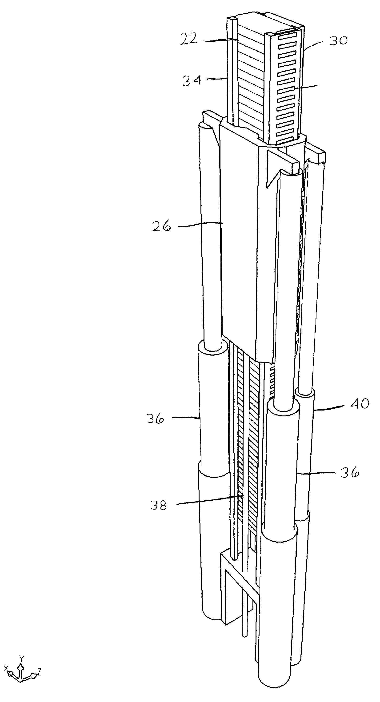
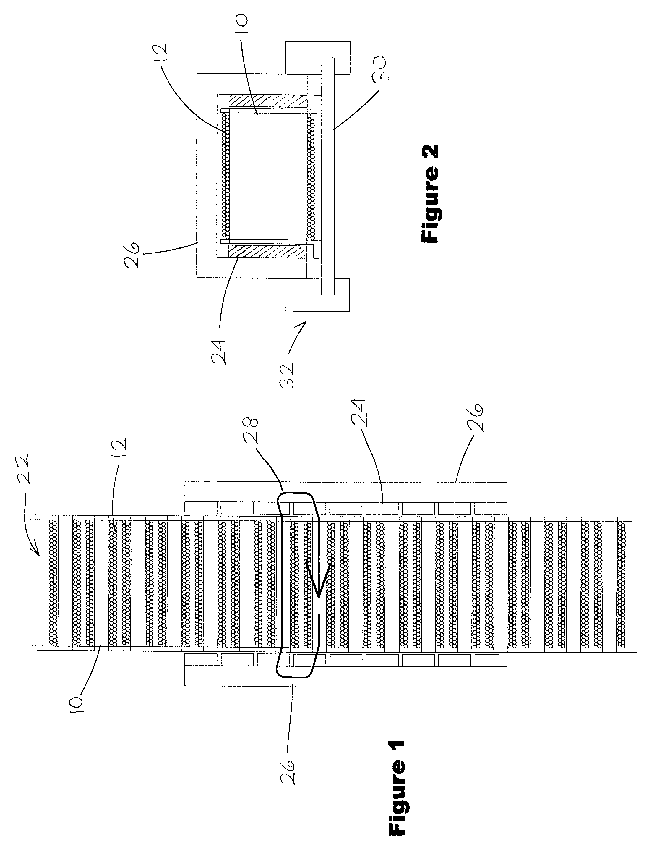
[0045]An embodiment of the motor of the present invention is illustrated in FIG. 1 (side section view) and FIG. 2 (end view), which show a single-phase permanent magnet linear motor with permanent magnets 24 mounted in moving magnet assembly 26, in opposition to the ends of laminated steel cores 10 and windings 12, whose flux axes, as shown by flux path 28, are perpendicular to the direction of travel. Laminated steel cores 10 are mounted rigidly with respect to motor frame 30. The moving magnet assembly is supported by linear bearing 32.

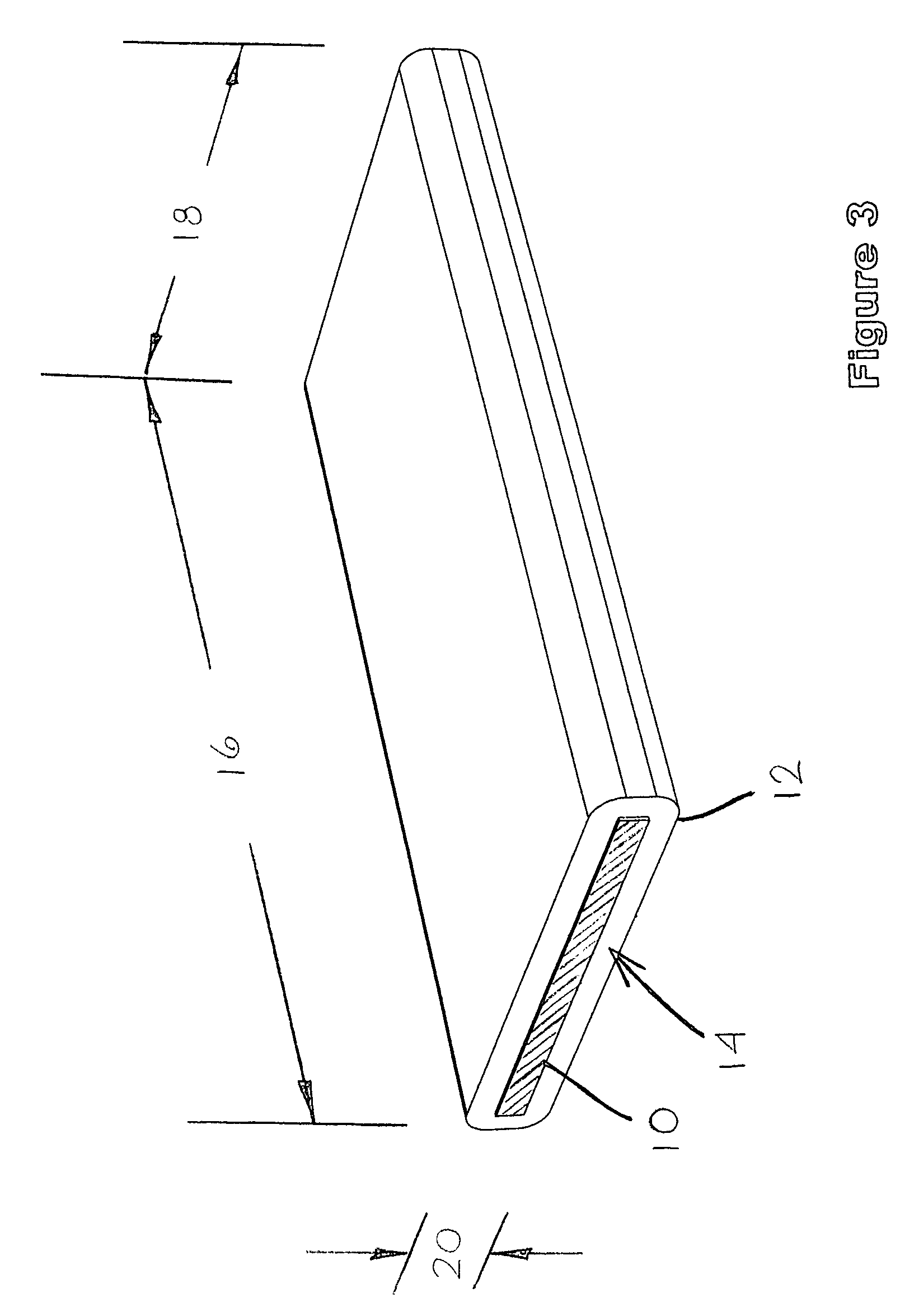
[0046]FIG. 3 shows a perspective view of an individual core / winding unit, a length dimension 16, a width dimension 18, a height dimension 20, a laminated steel core 10, a core cross-sectional area 14 (crosshatched), and a winding 12.

[0047]FIGS. 4...


PUM


Abstract

A high-efficiency permanent magnet linear motor optimized for low speed, high thrust applications, and a direct-drive oil well lift device powered by the motor. The motor comprises a high ratio of conductor volume to core cross-section area (14) and a plurality of individual, rectangular core-winding units (22) with a straight flux path through the cores (10) of the winding units.

Description

CROSS-REFERENCE TO RELATED APPLICATIONS[0001]This application claims the benefit of my Provisional Patent Application Ser. No. 60 / 837,184 filed Aug. 14, 2006.STATEMENT REGARDING FEDERALLY SPONSORED RESEARCH OR DEVELOPMENT[0002]Not applicable.SEQUENCE LISTING[0003]Not applicable.BACKGROUND OF THE INVENTION[0004]Most prior art linear motors are optimized by design for high resolution positioning, rapid acceleration, high speed, and / or low force ripple. These prior art linear motors yield low energy efficiencies when operated in a high relative thrust / low speed mode. Other prior art linear motors have a closed tubular mechanical configuration that is not optimum for attaching and interfacing to external equipment such as bearings, loads and counterbalances. Tubular linear motors are also limited in terms of energy efficiency in a high relative thrust / low speed mode.[0005]Prior art linear-motor powered oil well surface units for sucker rod actuation suffer from low energy efficiency, an...

Claims


Application Information

Patent Timeline
IPC IPC(8): H02K41/02
CPCH02K41/03
Inventor RAOS, DAVOR JACK
Owner RAOS DAVOR JACK
Why Eureka
Try Eureka