Compensation Of Gain Variations In A Multistage Optical Amplifier

a multi-stage, optical amplifier technology, applied in the direction of optical transmission with multiple stages, electromagnetic transmission, transmission, etc., can solve the problems of affecting the power supply of the amplifier, affecting the performance of the amplifier, and causing the amplifier to fail to meet the requirements of the input power

Active Publication Date: 2008-02-14
XIEON NETWORKS SARL
View PDF4 Cites 15 Cited by
  • Summary
  • Abstract
  • Description
  • Claims
  • Application Information

AI Technical Summary

Benefits of technology

[0005] Optical links and networks of said type frequently employ Wavelength Division Multiplexing (WDM), a technique whereby a plurality of channels—as a rule 40 or 80 are transmitted in an optical fiber 2 simultaneously. The information is therein modulated on a carrier wavelength of the respective channel for example at 10 Gbps. WDM furthermore offers the possibility of linking distributed transmitters and receivers directly over optical paths without the need for opto-electric conversion at the nodal points.

Problems solved by technology

The addition and removal or coupling and decoupling of individual channels of the WDM signal being transmitted on the fiber 2 results in abrupt changes in power at the input of the amplifier 3.
Particularly in the case of multistage amplifiers the deviations in gain in the individual stages can accumulate so that bit errors can very readily occur.

Method used


Image

  • Compensation Of Gain Variations In A Multistage Optical Amplifier
  • Compensation Of Gain Variations In A Multistage Optical Amplifier
  • Compensation Of Gain Variations In A Multistage Optical Amplifier

Examples


Embodiment Construction

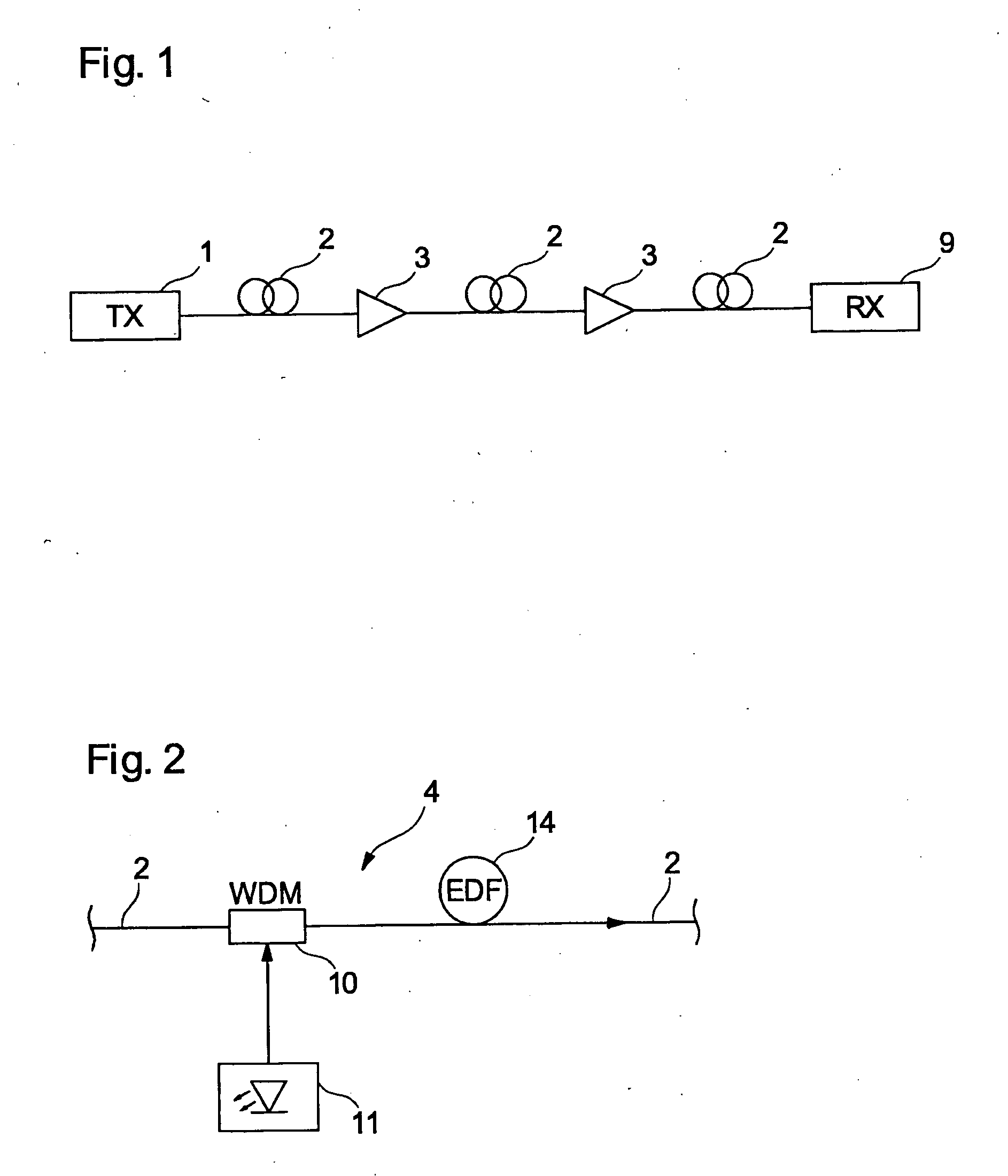
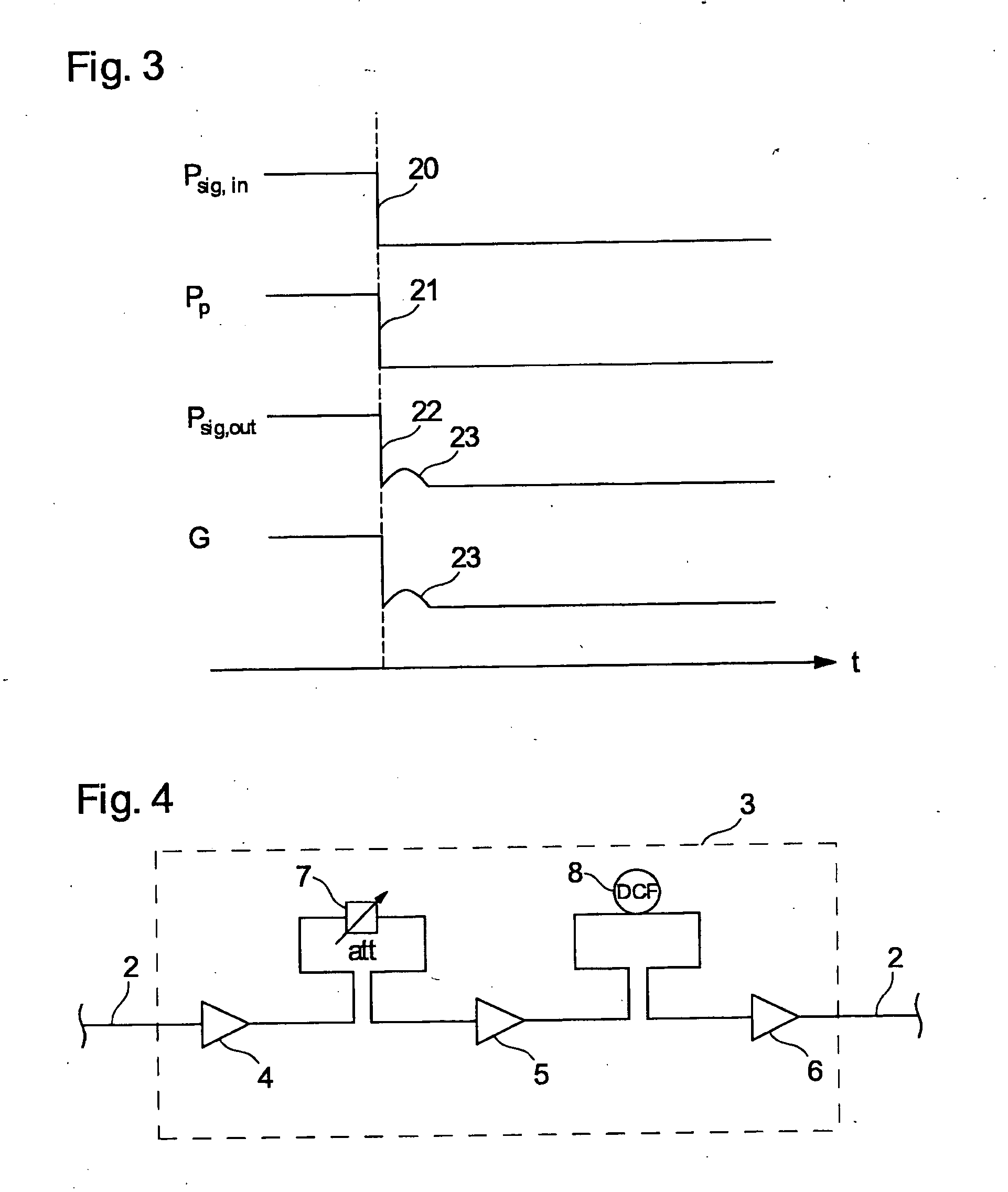
[0036] As regards the explanation of FIGS. 1 to 3, reference is made to the introduction to the description.

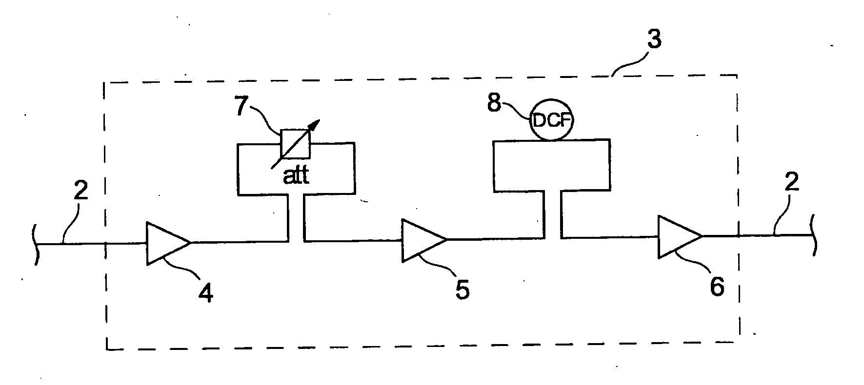
[0037]FIG. 4 shows a three-stage optical amplifier 3 having the amplifier stages 4, 5, and 6. Located between the amplifier stages 4 and 5 is a variable attenuator 7 by means of which the gain of the amplifier 3 can be varied.

[0038] Connected between the stages 5 and 6 is a dispersion-compensating fiber 8 (DCF) serving to compensate a dispersion, which is to say the variation in group speed as a function of frequency, of individual channels. Fibers of said type are usually several kilometers in length and wound into a packet connected between two amplifier stages. Owing to its length, the DCF fiber causes a certain signal delay, which is of significance here.

[0039] Connected to the input and output of the optical amplifier 3 is an optical fiber 2 on which is ducted an optical WDM signal having, for example, 80 channels. The individual amplifier stages 4-6 are in the present...


PUM


Abstract

There is described a method for compensation of gain variations in a multistage optical amplifier, for the amplification of an optical wavelength multiplex signal, comprising several amplifier stages in series, each with at least one pumping device. Gain variation occurring after a switching process can easily be compensated for, when the power jump expected at the second amplifier stage is determined and, depending thereon, a new pump power is calculated for the corresponding pump device, the new pump power is set for the pump device before the power jump arrives at the input of the second stage.

Description

CROSS REFERENCE TO RELATED APPLICATIONS [0001] This application is the US National Stage of International Application No. PCT / EP2005 / 055189, filed Oct. 12, 2005 and claims the benefit thereof. The International Application claims the benefits of German application No. 10 2004 052 883.7 DE filed Nov. 2, 2004, both of the applications are incorporated by reference herein in their entirety.FIELD OF INVENTION [0002] The invention relates to a method for compensating variations in gain in a multistage optical amplifier according to the preamble of claim 1 and to an appropriately set-up optical amplifier according to the preamble of claim 5. BACKGROUND OF INVENTION [0003] Optical amplifiers are employed in the field of optical transmission technology for amplifying the optical signals transmitted in an optical network. Said optical signals in many cases run over long links measuring several hundred kilometers and more in an optical fiber, being attenuated in the process. It is therefore n...

Claims


Application Information

Patent Timeline
Patent Type & Authority Applications(United States)
IPC IPC(8): H01S3/00H04B10/296
CPCH01S3/06758H04B2210/003H04B10/296H01S3/10015H01S3/1001H01S3/13013
Inventor RAPP, LUTZ
Owner XIEON NETWORKS SARL
Why Eureka
Try Eureka