Optical communition system with N + 1 redundancy

a technology of optical communication and redundancy, applied in multiplex communication, transmission monitoring, instruments, etc., can solve the problem of difficulty in a single standby interface being able to replace any active interface immediately, and achieve the effect of efficient replacemen

Active Publication Date: 2008-02-14
OKI ELECTRIC IND CO LTD
View PDF11 Cites 45 Cited by
  • Summary
  • Abstract
  • Description
  • Claims
  • Application Information

AI Technical Summary

Benefits of technology

[0012]An object of the present invention is to provide an optical communication system with a standby PON interface that can efficiently replace any of a plurality of active PON interfaces.

Problems solved by technology

A problem is that each PON interface operates according to its own control information, specifying such parameters as the round trip time between the OLT and each ONU, by which it controls transmissions so as to avoid collisions.
Differences between the control information held by different PON interfaces would make it difficult for a single standby interface to be capable of immediately replacing any active interface that failed.

Method used


Image

  • Optical communition system with N + 1 redundancy
  • Optical communition system with N + 1 redundancy
  • Optical communition system with N + 1 redundancy

Examples


Embodiment Construction

[0025]An embodiment of the invention will now be described with reference to the attached drawings, in which like elements are indicated by like reference characters.

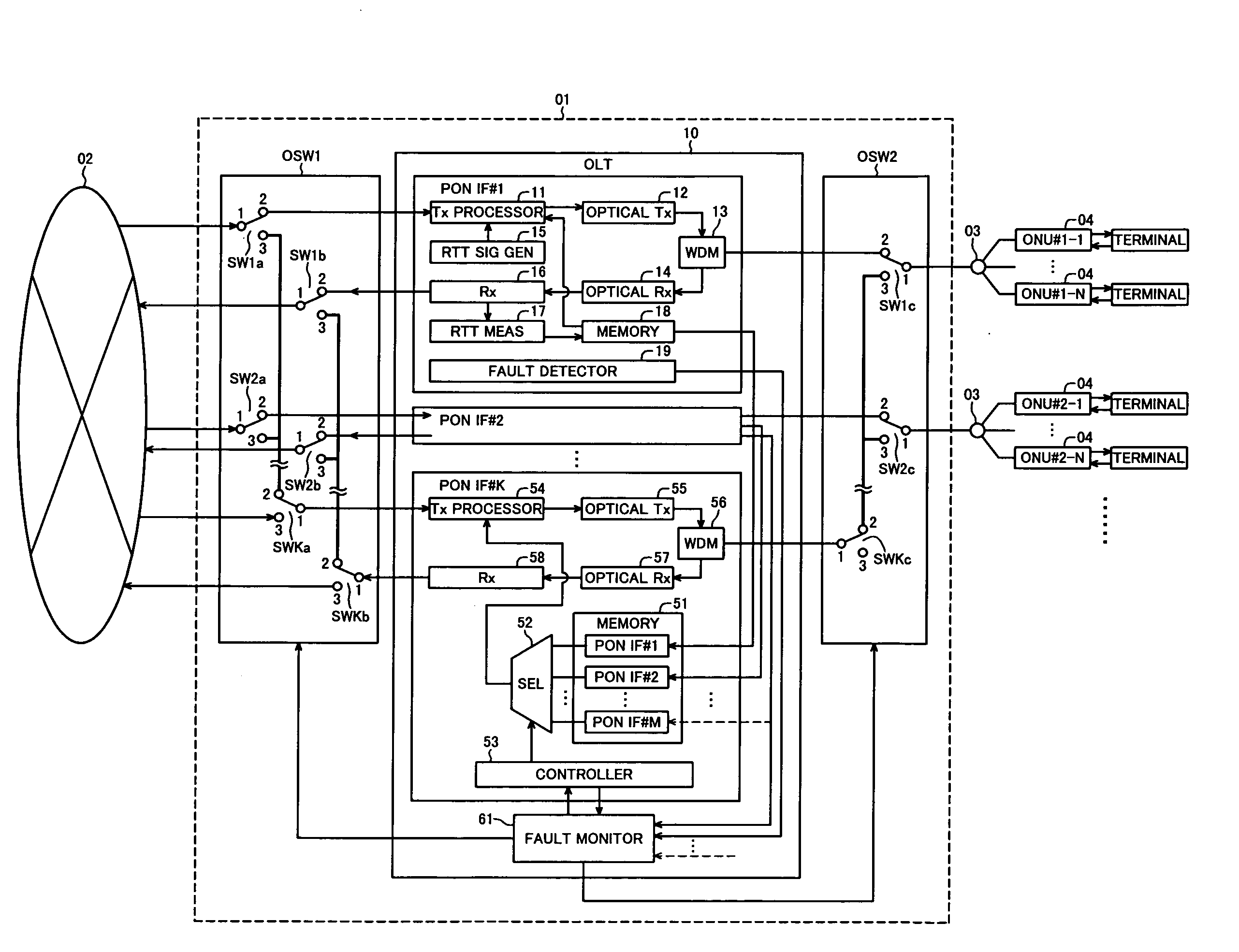
[0026]Referring to FIG. 3, the embodiment is a point-to-point optical communication system 01 comprising an optical line terminal (OLT) 10 and a pair of optical switching units OSW1, OSW2.

[0027]The OLT 10 may be installed in, for example, a telecommunication switching office operated by a telecommunication company and connected to a wide area network (WAN) 02 such as the Internet. The OLT 10 includes M interface cards PON IF#1 to PON IF#M (only PON IF#1 and PON IF#2 are shown) that control optical communication between the wide area network 02 and a plurality of optical network units (ONUs) 04 installed on subscriber premises, and a standby interface card PON IF#K that can function as a replacement for any of these M interface cards (M is an integer greater than unity). All of the interface cards are detachably mounted ...


PUM


Abstract

An optical communication system has two or more active interfaces, each controlling the transmission and reception of optical signals between a communication network and one or more subscriber terminals according to control information pertaining to the individual subscriber terminals. The control information used by all the active interfaces is stored in a memory. The optical communication system also has a standby interface that is functionally equivalent to the active interfaces, and an optical switching apparatus that switches data transmission paths among the network, the active and standby interfaces, and the subscriber terminals. If a fault is detected in an active interface, the standby interface extracts the control information of the faulty interface from the memory, and the optical switching apparatus switches the data transmission paths so that the standby interface replaces the faulty interface.

Description

BACKGROUND OF THE INVENTION[0001]1. Field of the Invention[0002]The present invention relates to a point-to-multipoint optical communication system with a standby interface that can be used in case of failure of another interface.[0003]2. Description of the Related Art[0004]The rapid build-up of an installed base of asymmetric digital subscriber lines (ADSL) and other broadband subscriber communication lines has led service providers to begin providing services that require high-speed communication. To expand these services, a still faster and more stable broadband infrastructure will be necessary, which makes the extension of optical fiber to the home (FTTH) increasingly attractive. A known means of providing FTTH service at a low cost is the passive optical network (PON), in which a plurality of users share a single optical fiber. The term PON designates a network with a star topology that uses a passive optical coupler to form a point-to-multipoint communication system.[0005]FIG....

Claims


Application Information

Patent Timeline
Patent Type & Authority Applications(United States)
IPC IPC(8): H04B10/08H04B10/03H04B10/032H04B10/27H04B10/272H04L12/44
CPCH04Q2011/0081H04Q11/0067
Inventor MUKOJIMA, TOSHIAKI
Owner OKI ELECTRIC IND CO LTD
Why Eureka
Try Eureka