[0006] It is therefore an object of the invention to provide a turbomachine having the characteristics described initially, in which the shaft is mounted in the shaft housing in a robust, low-maintenance, and simple manner.
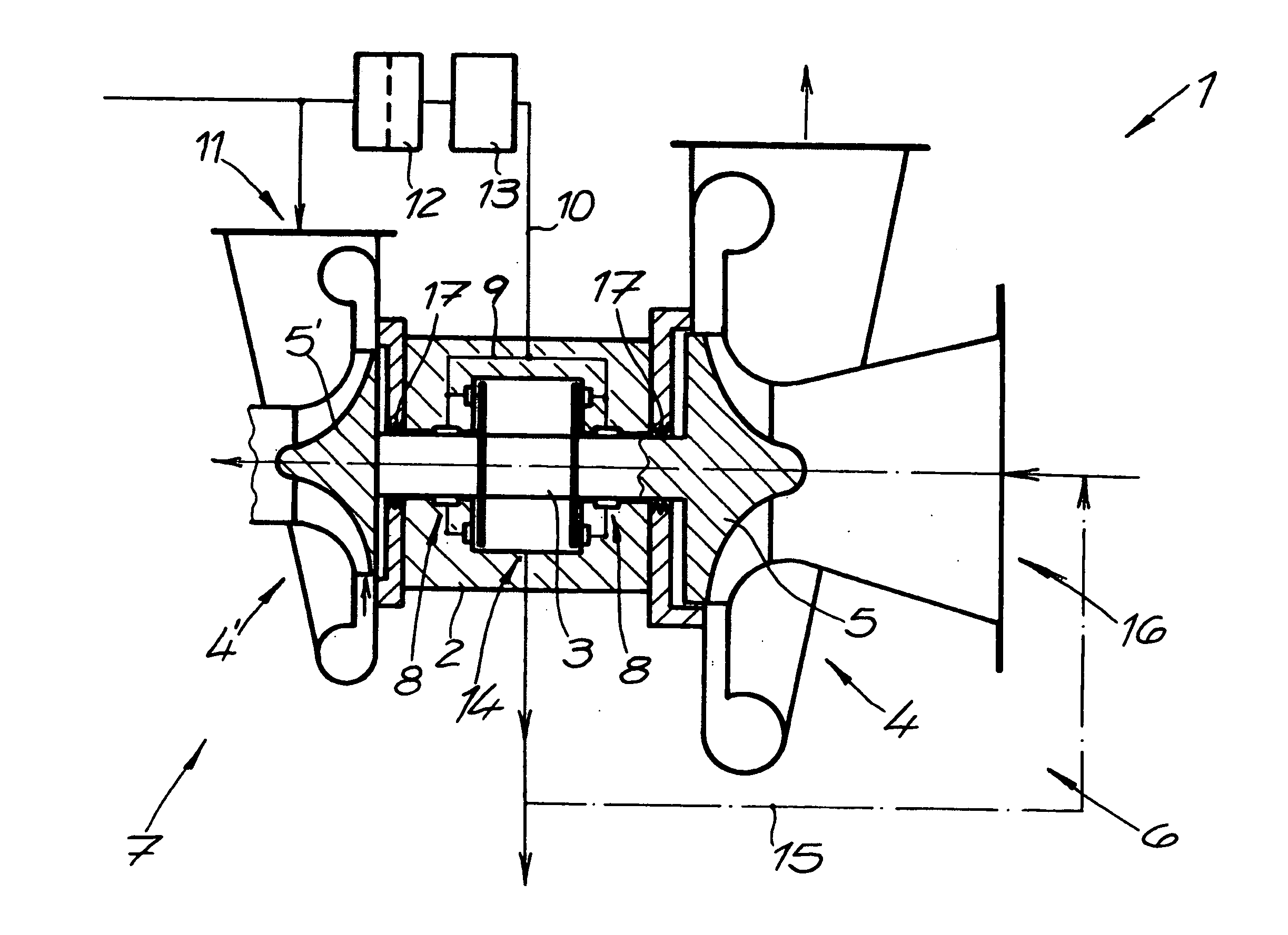
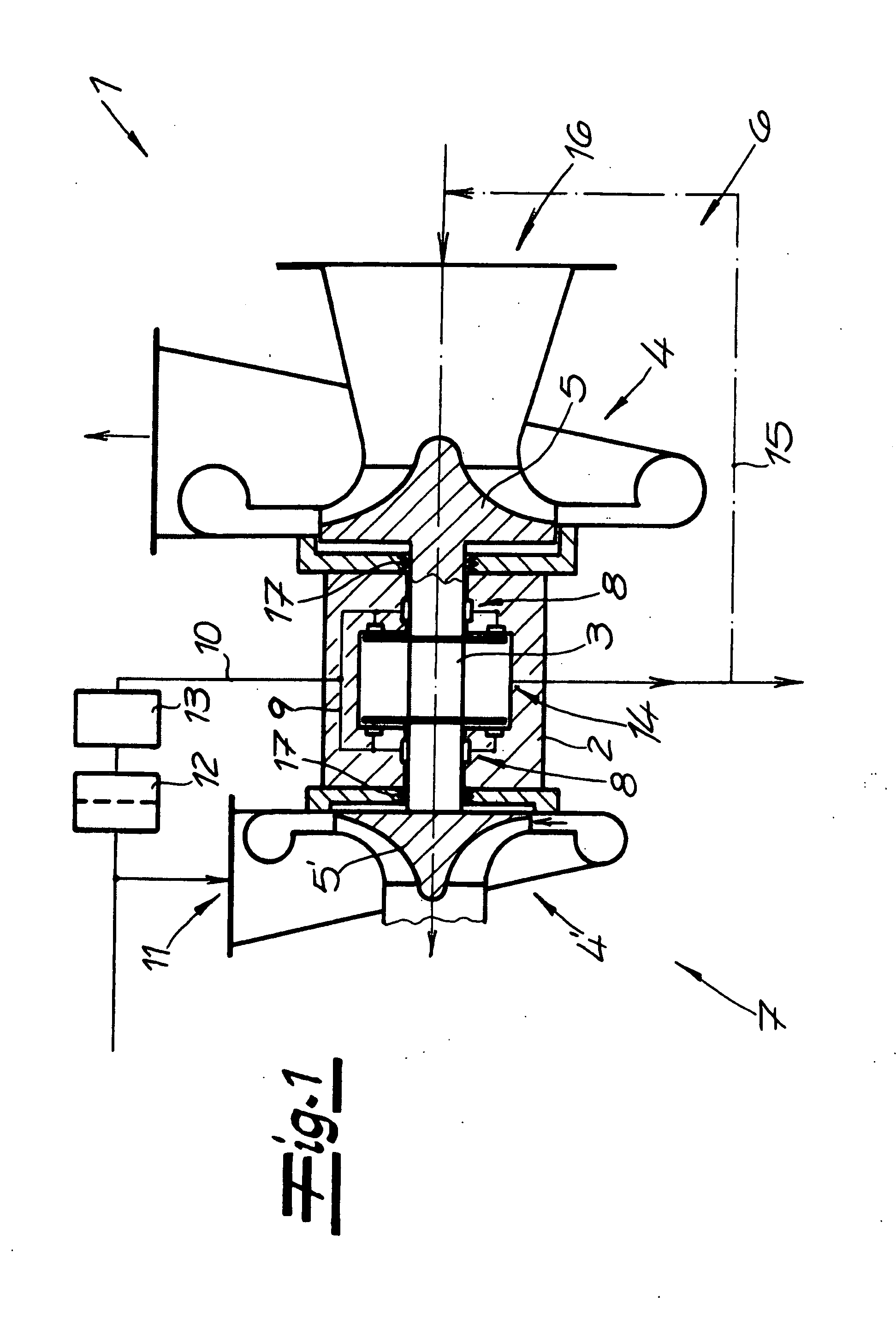
[0007] Proceeding from a turbomachine having the characteristics described initially, this task is accomplished, according to the invention, in that the bearings for axial and radial bearing of the shaft are configured as hydrostatic, gas-lubricated bearings. The shaft is mounted by means of the hydrostatic, gas-lubricated bearings in such a manner that the bearing effect is independent, or at least extensively independent of the speed of rotation of the shaft, thereby guaranteeing sufficient support of the shaft even during startup of the turbomachine, and good rigidity and low sensitivity to pressure surge stresses independent of the speed of rotation. The pressure in the connector to the compressed gas line is at least 5 bar greater than the pressure in the region of the ventilation connector. Since the bearing has a portion of the working gas applied to it, a separate compressed gas source is not provided, according to the invention. In comparison with a hydrodynamic, gas-lubricated bearing, the hydrostatic bearing is characterized by great rigidity and a lower sensitivity to pressure surge stresses. Fundamentally, the hydrostatic bearings can have a certain dynamic component, at high speeds of rotation, as a function of the design configuration. However, since the formation of a gas
cushion and a comparatively great bearing gap are provided in the case of the hydrostatic bearings, the dynamic component of the support force is typically less than 20%, preferably less than 10%, even at the maximal speed of rotation. The dynamic component of the support force can be determined by a comparison of the forces that act on a bearing in the
rest state, in total, and at the maximal speed of rotation. While elastic spring, sheet-
metal, or film elements are preferably used in the case of hydrodynamic bearings, which can rest resiliently against the rotor in order to form the smallest possible bearing gap of typically a few μm, it is usually provided, within the scope of the invention, that the bearing surfaces are formed from a rigid material. Preferably, no additional bearings are provided, so that the entire shaft is mounted hydrostatically. The invention is based on the recognition that the bearing properties can be improved both at low speeds of rotation and at high speeds of rotation, by means of an exclusively or almost exclusively hydrostatic bearing method. In order to achieve this, however, a
pressure difference of at least 5 bar must be present between the connector to the compressed gas lines and the region of the ventilation connector, according to the invention. The bearing arrangement, which is particularly simple in design, reliable, and robust, is particularly suitable for cryogenic applications. These include, without restriction, the cryogenic
fractionation of air, and the
liquefaction of its components, as well as the
liquefaction and re-
liquefaction of
hydrocarbon gases, for example
natural gas.
[0008] Because of the simple, robust configuration of the bearing, the risk of bearing damage is minimized. The embodiment according to the invention is particularly suitable for turbomachines having a simple construction, or for oil-free turbomachines in which a fluid-lubricated bearing is not a possibility.
[0009] In one embodiment, the portion of the working gas that is guided through the compressed gas line is passed out of the turbomachine after it has flowed through the bearings, through the ventilation connector. Such an embodiment can be particularly advantageous if only a small portion of the working gas is needed for lubricating the bearing. Preferably, however, the ventilation connector is connected with a low-pressure region of the turbomachine, and thus the portion of the working gas utilized for
lubrication of the bearing remains in the turbomachine. Within the framework of this embodiment, it is particularly possible to construct the turbomachine so that it is hermetically sealed, at least to a great extent, with no seals or only simple seals being required. In this case,
operational safety can be greatly increased, particularly in the case of toxic, combustible, or explosive working gases, and environmental
contamination due to a
gas leak can be reliably prevented.
[0012] In a preferred embodiment of the invention, the compressed gas line has a
pressure regulator or amount flow
regulator. Pressure variations in the pressure region of the turbomachine with which the compressed gas line is connected can be compensated by means of such a
regulator, and the bearing properties can be regulated as a function of the load. In particular, the stiffness and the damping behavior of the bearing can be adjusted to an optimal value with the
pressure regulator, in accordance with the requirements. It is particularly preferred that the
pressure regulator or amount flow
regulator can be controlled electronically, and that it is connected with an assigned control device, which allows flexible
adaptation of the pressure or the amount of flow during operation, proceeding from measurement signals, control signals and / or manual input.
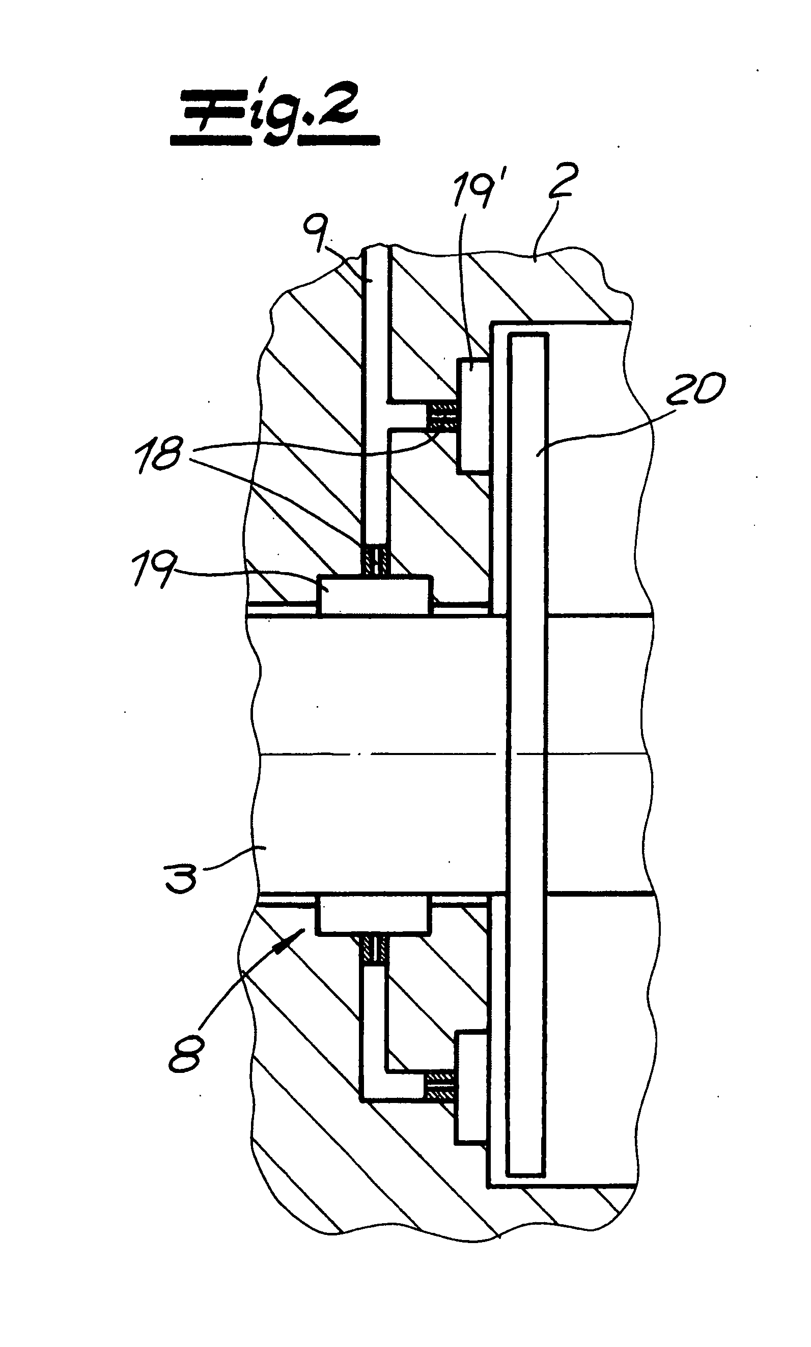
[0013] In order to protect the bearings from
contamination and therefore from possibly increased wear, a filter is preferably disposed in the compressed gas line. The bearing surfaces connected with the compressed gas line are preferably formed in the shaft housing, thereby achieving a particularly simple construction.



