
Scroll Compressor

Inactive Publication Date: 2008-02-14
PANASONIC CORP
View PDF2 Cites 18 Cited by
  • Summary
  • Abstract
  • Description
  • Claims
  • Application Information

AI Technical Summary

Benefits of technology

[0007]With this aspect, if the ratio (d / D) is set greater than 0.5, even if the magnitude of discharge pressure is varied due to the operation condition, plus (+) thrust force can always be obtained. Therefore, it is possible to bring the orbiting scroll into contact and slide with the fixed scroll only by the discharge pressure Pd applied to the inner region of the annular seal. With this, the pressure Pm applied to the outer region of the annular seal can be set to the same value as the suction pressure Ps or a value close to the suction pressure Ps. As a result, when the compressor is started, lubricant oil supplied to the outer region of the annular seal is supplied to the suction space substantially simultaneously. Therefore, the supply delay of lubricant oil is eliminated, and even if refrigerant liquid is sucked into the suction space from the initial stage of the start, the sliding surface is not seized up.
[0009]According to this aspect, if the lubricant oil flows from the inner region of the annular seal into the outer region, the pressure Pm in the outer region rises. If the set pressure Pm is low pressure (i.e., suction pressure Ps or pressure close to the suction pressure Ps), the pressure reaches such a value within a short time. Therefore, the pressure is set to 0.2((P / Po(0, i.e., Ps+0.2(Po(Pm(Ps using the saturation vapor pressure Po (constant value) when a refrigerant to be used is at 0(C. By setting the set back pressure of the outer region small in this manner, the pressure in the outer region of the annular seal reaches the set value within a short time and then, lubricant oil is also supplied to the suction space of the compressor mechanism swiftly. Thus, the supply delay of the lubricant oil to the suction space is reduced. Even if refrigerant liquid is sucked into the suction space from the initial stage of start, the sliding surfaces are not seized up.
[0011]According to this aspect, even when refrigerant gas including liquid refrigerant is sucked at the time of start, lubricant oil can be supplied swiftly at the time of start if dryness parameter of the refrigerant gas is 0.5 or less. With this, the reliability of the scroll compressor can be secured.
[0013]According to this aspect, when CO2 is used as the refrigerant, since its pressure is high, thrust force for pushing the orbiting scroll against the fixed scroll is increased and the sliding surfaces are prone to be seizured correspondingly. However, if the back pressure (P in the outer region is set small, the back pressure rises to the set value within a short time, the lubricant oil is swiftly supplied to the suction space thereafter, and it is possible to prevent the sliding surfaces from being seizured.

Problems solved by technology

When lubricant oil is not supplied to the suction space 9 at the time of starting of the scroll compressor, if a large amount of refrigerant liquid is returned to the suction space 9 from the refrigeration cycle together with refrigerant gas, there is a problem that lubricant oil remaining on a sliding surface is washed away and as a result, and the fixed scroll 4 or the orbiting scroll 5 is damaged and seized up.
Therefore, a duration of lubrication delay becomes longer as compared with refrigerant R410A and thus, there is a problem that the fixed scroll 4 and orbiting scroll 5 are more prone to be seized up.

Method used


Image

  • Scroll Compressor
  • Scroll Compressor
  • Scroll Compressor

Examples


first embodiment

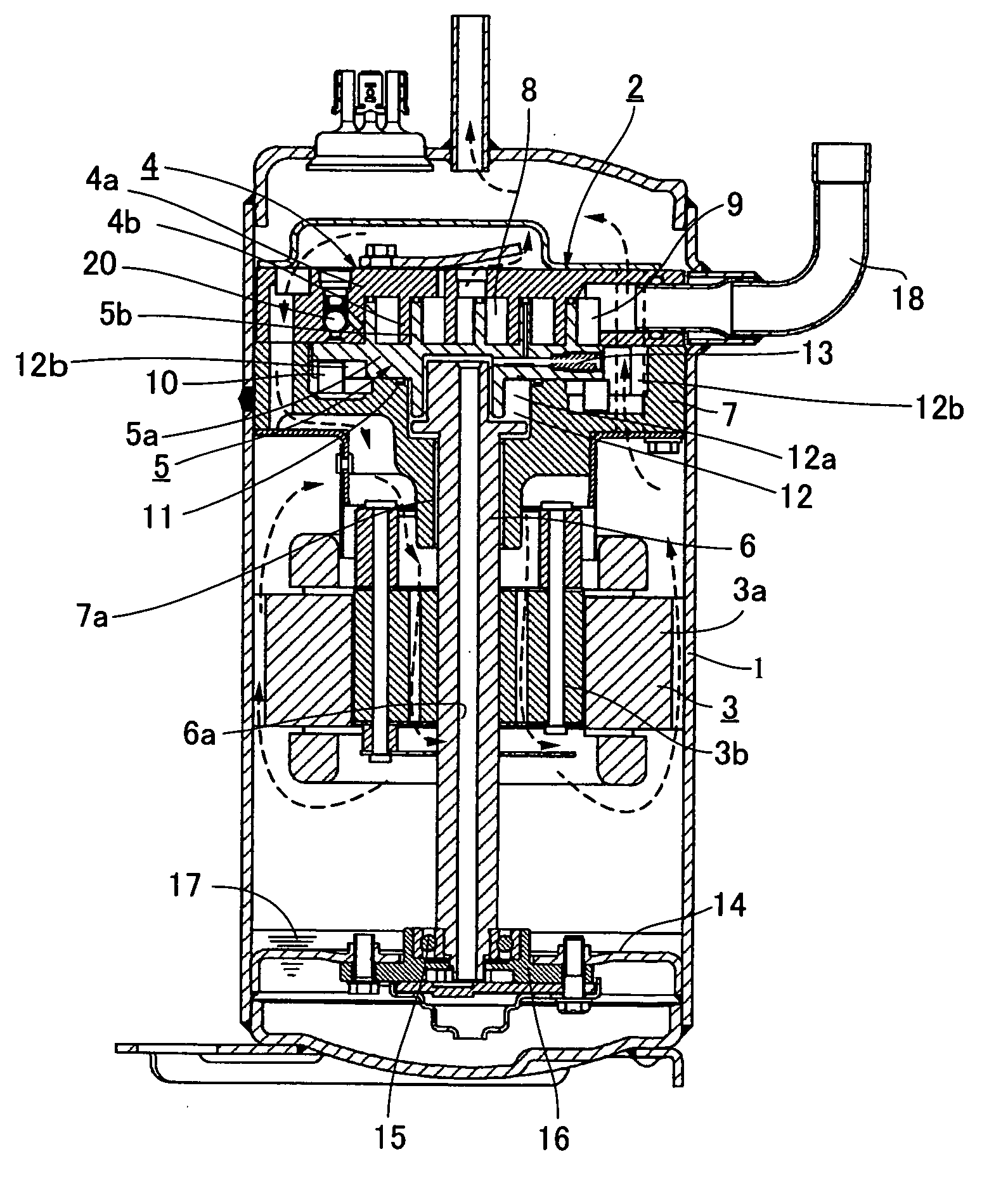
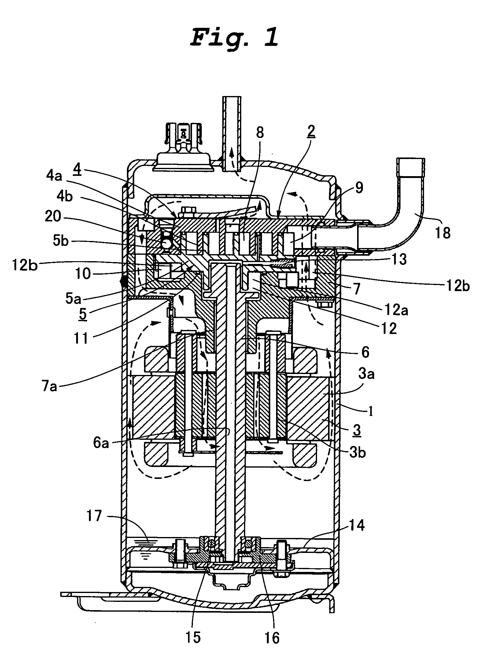
[0020]FIG. 1 is a vertical sectional view of a scroll compressor according to a first embodiment of the present invention. A material to be compressed is refrigerant gas.

[0021]As shown in FIG. 1, the scroll compressor of the embodiment includes a main bearing member 7 of a crankshaft 6 fixed in a container 1 by welding or shrink fitting, a fixed scroll 4 fixed on the main bearing member 7 by means of a bolt, an orbiting scroll 5 combining with the fixed scroll 4, and a scroll compression mechanism 2 formed by sandwiching the orbiting scroll 5 between the main bearing member 7 and the fixed scroll 4. A rotation-restraint member 10 is provided between the orbiting scroll 5 and the main bearing member 7. The rotation-restraint member 10 comprises an Oldham ring, and prevents the orbiting scroll 5 from rotating and guides the orbiting scroll 5 such that the orbiting scroll 5 orbits. The orbiting scroll 5 is eccentrically driven by an eccentric portion provided on an upper end of the cra...

second embodiment

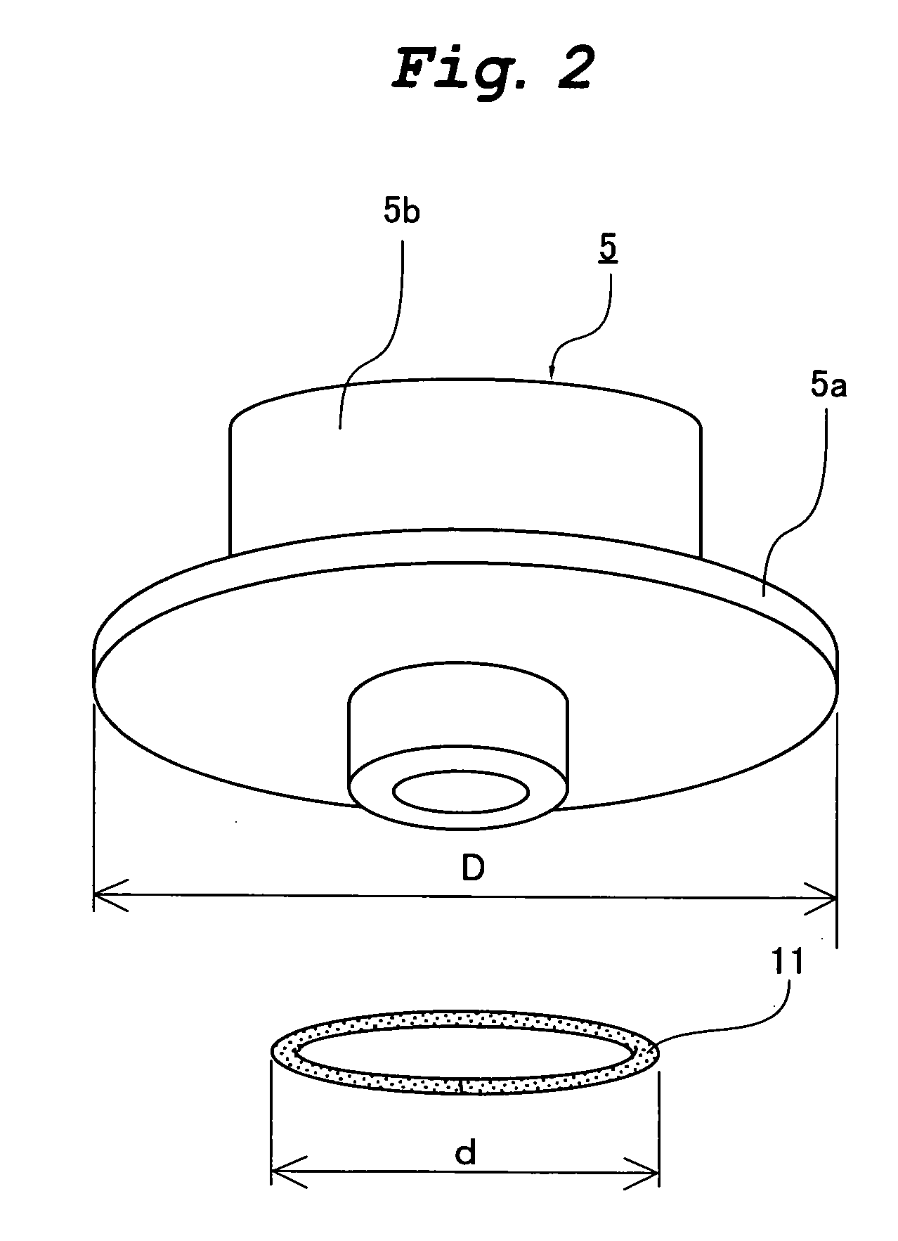
[0031]Next, a scroll compressor of a second embodiment of the invention will be explained. In the second embodiment, the back pressure ΔP (=Pm−Ps) applied to the outer region 12b of the annular seal 11 shown in the scroll compressor of the first embodiment in FIG. 1 is set in the following manner. Constituent members having the same functions as those of the scroll compressor of the first embodiment are designated with the same reference symbols, and explanation thereof will be omitted.

[0032]Lubricant oil flows into the outer region 12b of the annular seal 11 from the inner region 12a, and the pressure in the outer region 12b rises, but as a set pressure of the back pressure is lower, the pressure in the outer region 12b reaches that value within a short time. When the pressure in the outer region 12b of the annular seal 11 rises to the set back pressure, the lubricant oil is supplied to the suction space 9 of the compression mechanism 2. Therefore, in the second embodiment, the val...


PUM


Abstract

A back pressure chamber 12 provided on a back surface of an orbiting scroll 5 is divided into an inner region 12a and an outer region 12b by an annular seal 11. A diameter d of the annular seal 11 is set 0.5 times or more of a diameter D of an orbiting mirror plate 5a. With this, plus thrust force can be applied to the orbiting scroll 5 irrespective of magnitude of a discharge pressure Pd applied to the inner region 12a. Therefore, it is possible to push the orbiting scroll 5 against the fixed scroll 4 only by back pressure of discharge pressure. A set pressure Pm of the outer region 12b is reduced to a value close to a suction pressure Ps, a pressure adjusting mechanism 20 is swiftly opened after a scroll compressor is started. With this, lubricant oil is supplied from the outer region 12b to the suction space 9 without a time lag.

Description

TECHNICAL FIELD[0001]The present invention relates to a scroll compressor used for a refrigeration cycle apparatus, and more particularly, to a scroll compressor suitable for a vapor-compression refrigeration cycle using R410A, carbon dioxide (CO2) and the like as a refrigerant.BACKGROUND TECHNIQUE[0002]In the conventional scroll compressor of this kind, to reduce leakage loss in a compressed chamber and to obtain high efficiency, an orbiting scroll is brought into contact and slide with a fixed scroll, and the compressed chamber is sealed in many cases. FIG. 5 shows an example of a conventional structure described in patent document 1 (Japanese Patent Application Laid-open No. 2001-280252). That is, in the conventional scroll compressor, a back pressure chamber 12 is provided on a surface on the opposite side (back surface) from an orbiting scroll wrap surface of an orbiting scroll 5. The back pressure chamber 12 is divided into an inner region 12a and an outer region 12b by an ann...

Claims


Application Information

Patent Timeline
IPC IPC(8): F04C18/02F04C23/00F04C27/00F04C29/02F25B1/00F25B1/04
CPCF04C18/0215F04C29/023F04C27/005F04C23/008F04C18/02
Inventor SAWAI, KIYOSHIIIDA, NOBORUFUTAGAMI, YOSHIYUKIHIWATA, AKIRAAKAZAWA, TERUYUKI
Owner PANASONIC CORP
Features
  • Generate Ideas
  • Intellectual Property
  • Life Sciences
  • Materials
  • Tech Scout
  • Unparalleled Data Quality
  • Higher Quality Content
  • 60% Fewer Hallucinations
Learn More