Tethered Self-Expanding Stent Delivery System

a self-expanding, stent technology, applied in the field of tethered self-expanding stent delivery system, can solve the problems of stent not being moved or repositioned, stent movement is gradually exposed in a relatively slow unidirectional manner, and the vessel wall cannot be moved or repositioned, so as to minimize the phenomenon of “push-pull” and minimize the movement of the sten

Inactive Publication Date: 2008-02-14
MEDLOGICS DEVICE CORP
View PDF6 Cites 29 Cited by
  • Summary
  • Abstract
  • Description
  • Claims
  • Application Information

AI Technical Summary

Benefits of technology

[0014]The devices, systems and methods of the present invention address the above-identified problems associated with commonly-used self-expanding stent delivery systems. First, the devices, systems and methods of the present invention can minimize stent movement during deployment, thus helping to enable more accurate positioning of the stent at the vessel treatment site. Second, the methods and systems of the present invention can reduce the “spring effect” and resulting “jump” of the stent caused by the spring effect. Third, the methods and systems of the present invention can minimize the “push-pull” phenomenon associated with commonly-used self-expanding stent delivery systems. Finally, the devices, systems and methods of the present invention can improve the deliverability of self-expanding stents by providing more flexible delivery catheter ends with smaller diameters.

Problems solved by technology

Unfortunately, while the affected vessel can be enlarged thus improving blood flow, in some instances the vessel recloses chronically (“restenosis”), closes down acutely (“abrupt reclosure”) or reoccludes (all hereinafter referred to as “reclosure”), negating the positive effect of the angioplasty procedure.
While such reclosure does not occur in the majority of cases, it occurs frequently enough that such complications comprise a significant percentage of the overall failures of the angioplasty procedure, for example, twenty-five to thirty-five percent of such failures.
A problem with the described stent delivery catheters and systems is that as the outer retractable sheath is withdrawn, the self-expanding stent is gradually exposed in a relatively slow unidirectional manner from the distal end of the self-expanding stent towards its proximal end.
This effect of outer retractable sheaths causes a number of clinical problems during deployment of a self-expanding stent.
For example, when the distal end of a self-expanding stent is exposed and allowed to expand before the rest of the stent, the distal end of the stent may contact the vessel wall before the rest of the stent is deployed, resulting in an “anchoring edge.” Once such an “anchoring edge” is created, the stent should no longer be moved or repositioned because any further movement can cause irritation and trauma to the vessel wall (caused by the metallic stent edges moving against the delicate inner surface of the vessel wall).
Therefore, when using most currently-available stent designs, once the distal end of the stent is fully expanded, the stent is essentially locked into a position and further repositioning is problematic.
The inability to reposition a stent with such an “anchoring edge” is compounded by another problem created by outer retractable sheaths, i.e. the “spring effect.” The “spring effect” occurs when the withdrawal of an outer retractable sheath causes a self-expanding stent to behave like a spring.
This sudden release can cause the stent to move in a distal direction in an unpredictable way, an effect that can be exaggerated in self-expanding stents having a short overall length.
Another difficulty that can be encountered during the release of self-expanding stents when using conventional delivery systems is related to a “push-pull” phenomenon.
In practical terms, the “push-pull” effect can result in the forward motion of the self-expanding stent thereby also resulting in inaccurate positioning.
These features can negatively affect the deliverability of self-expanding stents in at least two ways.
First, the stiff nature of outer retractable sheaths provides less flexible delivery catheters that are more difficult to navigate through curved vessels.
Second, the presence of an outer retractable sheath around the outside of a compressed self-expanding stent increases the diameter of the delivery catheter.
This increase also can negatively affect the deliverability of the stent.

Method used


Image

  • Tethered Self-Expanding Stent Delivery System
  • Tethered Self-Expanding Stent Delivery System
  • Tethered Self-Expanding Stent Delivery System

Examples


Embodiment Construction

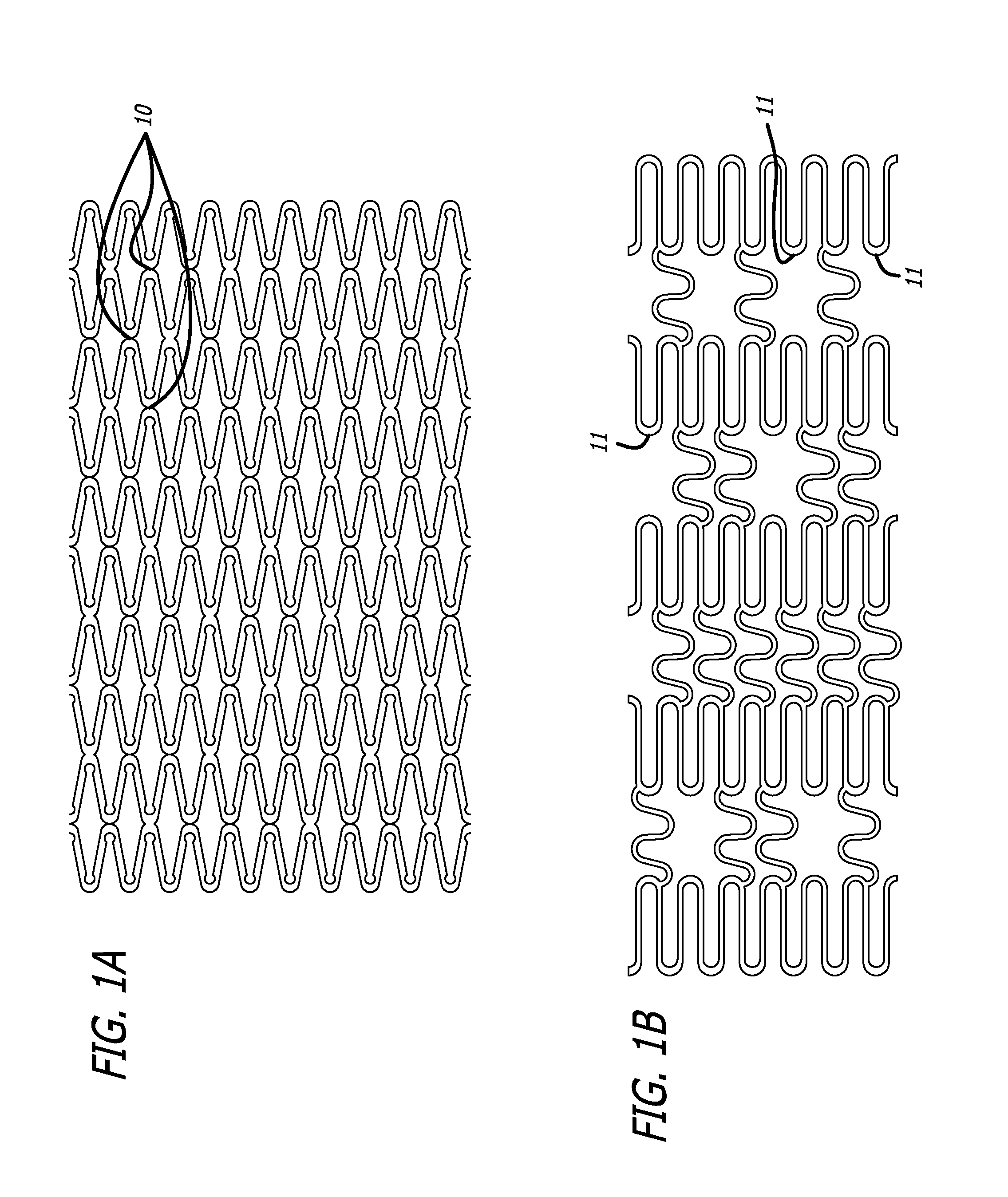
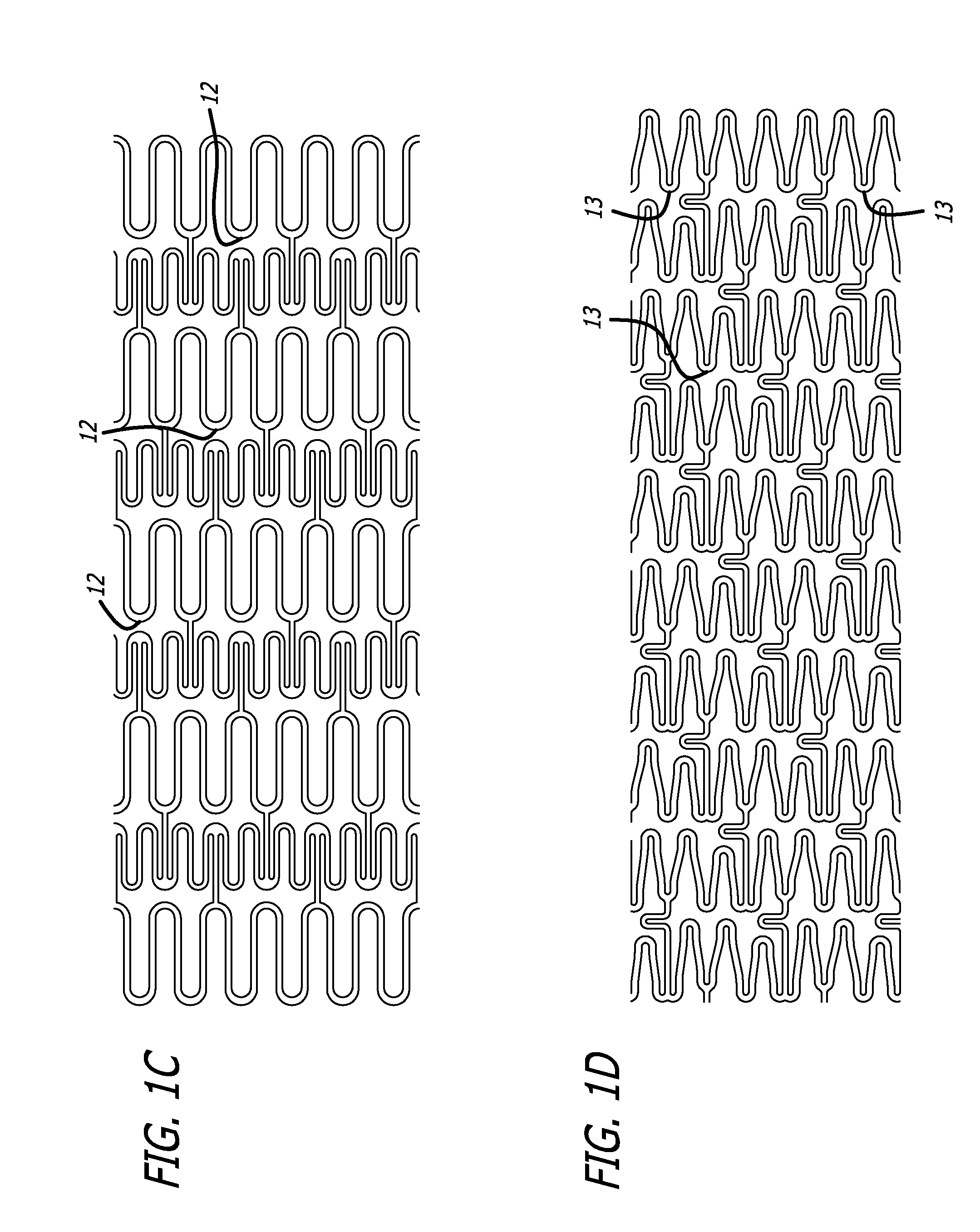
[0042]FIGS. 1A-1D depict four different exemplary stent configurations useful in accordance with the teachings of the present invention. The stents used in accordance with the present invention can have more or less undulations and / or sections than are shown in FIGS. 1A-1D but these simplified depictions are sufficient to illustrate the present invention. In these examples depicted in FIGS. 1A-1D, the stent bodies are unitary, meaning that they are fashioned from a single piece of material. For example, the stent bodies are cut to an appropriate length from appropriate material tubing. The tubing is then laser cut to form the strut pattern. In another embodiment of the present invention, the stent bodies need not be unitary but instead can consist of individual segments joined by welding, soldering, adhesive bonding, mechanical fastening, or in any other suitable way.

[0043]Once a stent body configuration is chosen, a device with an appropriately-sized and spaced slotted design can b...


PUM


Abstract

The present invention relates to devices, systems and methods to maintain self-expanding stents in a compressed form during delivery to and positioning at a treatment site. The devices, systems and methods of the present invention can provide for more accurate stent positioning and can improve the deliverability of self-expanding stents. Designs of the devices, systems and methods of the present invention include slotted designs, tethered designs and encapsulating flexible sheath designs.

Description

FIELD OF THE INVENTION[0001]The present invention relates to devices, systems and methods to maintain self-expanding stents in a compressed form during delivery to a treatment site. The devices, systems and methods of the present invention can provide for more accurate stent positioning and can improve the deliverability of self-expanding stents.BACKGROUND OF THE INVENTION[0002]Cardiovascular disease, including atherosclerosis, is the leading cause of death in the United States. The medical community has developed a number of methods and systems for treating coronary disease, some of which are specifically designed to treat the complications resulting from atherosclerosis and other forms of coronary artery narrowing.[0003]An important development for treating atherosclerosis and other forms of vascular narrowing is percutaneous transluminal angioplasty, and, in the specific instance of coronary artery disease, percutaneous transluminal coronary angioplasty, hereinafter collectively ...

Claims


Application Information

Patent Timeline
Patent Type & Authority Applications(United States)
IPC IPC(8): A61F2/06
CPCA61F2/91A61F2/95A61F2002/9511A61F2002/9505A61F2/958
Inventor PEACOCK, JAMES C.LEE, MICHAEL J.
Owner MEDLOGICS DEVICE CORP
Why Eureka
Try Eureka