Refrigerant cycle device with ejector

Inactive Publication Date: 2008-02-21
DENSO CORP
View PDF7 Cites 63 Cited by
  • Summary
  • Abstract
  • Description
  • Claims
  • Application Information

AI Technical Summary

Benefits of technology

[0006]In consideration of the above problems, it is an object of the present invention to provide a refrigerant cycle device, which c

Problems solved by technology

However, the above technique involves a problem.
In this case, though defrosting is more effectively carried out at the second evaporator than at the first evaporator, the temperature is needl

Method used


Image

  • Refrigerant cycle device with ejector
  • Refrigerant cycle device with ejector
  • Refrigerant cycle device with ejector

Examples


first embodiment

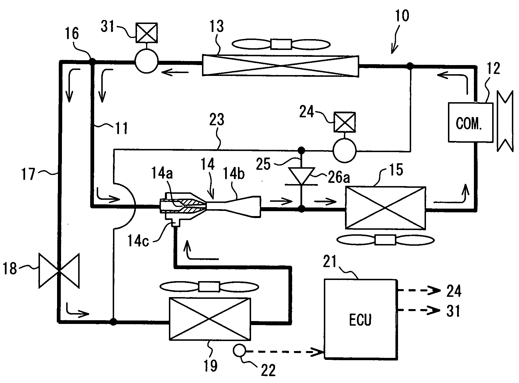
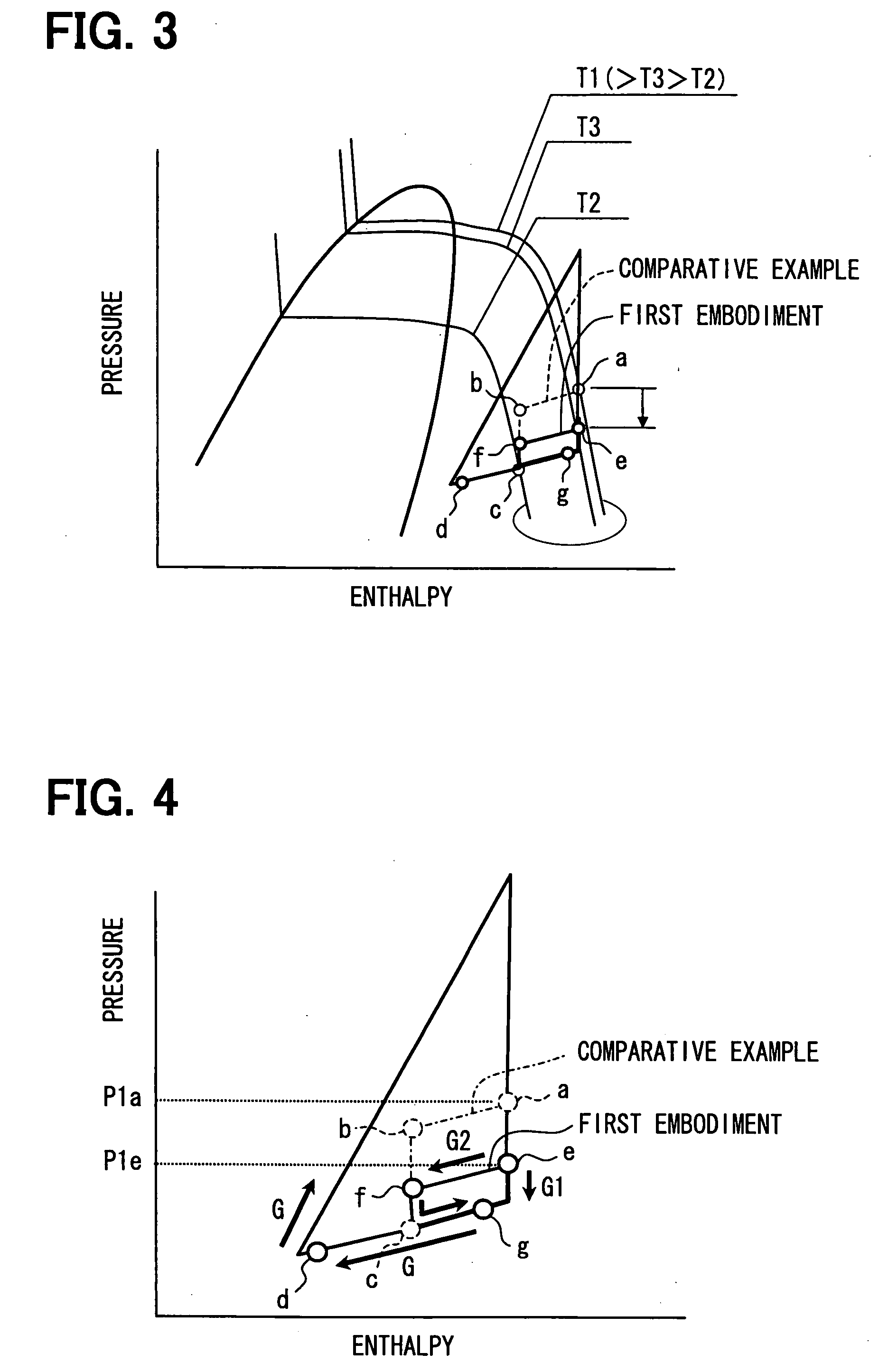
[0042]A first embodiment of the present invention will be now described with reference to FIGS. 1 to 5.

[0043]FIG. 1 illustrates an example in which a vapor-compression refrigerant cycle device 10 of the first embodiment is typically used for a refrigeration cycle of an air conditioner for vehicles. The refrigerant cycle device 10 is provided with a refrigerant circulation passage 11, and a compressor 12 that sucks in and compresses refrigerant is located in the refrigerant circulation passage 11.

[0044]The compressor 12 is rotationally driven by a vehicle running engine, not shown, through a belt or the like. For the compressor 12, a variable displacement compressor whose refrigerant discharging capacity can be adjusted by change in a discharge capacity may be used. A discharge capacity of refrigerant discharged from the compressor 12 is equivalent to a refrigerant discharge quantity per rotation. The discharge capacity can be changed by changing a capacity for sucking in refrigerant...

second embodiment

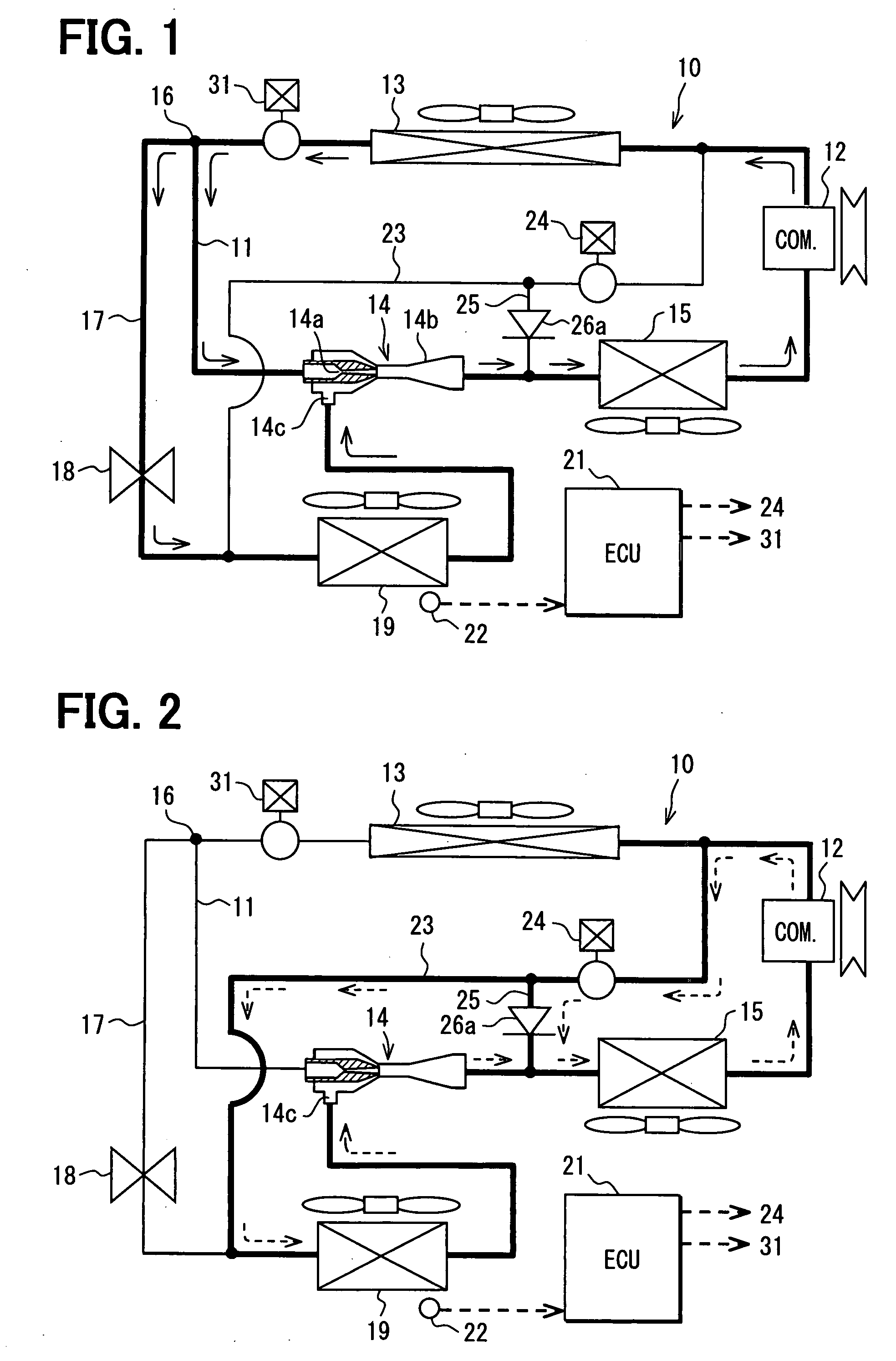
[0080]FIG. 6 and FIG. 7 illustrate a second embodiment of the invention. The second embodiment is implemented by replacing the check valve 26a in the first embodiment with an on-off switching valve 26b (flow control unit, backward flow preventing means).

[0081]The on-off switching valve 26b is a valve installed in the branch passage 25, the opening / closing of which is controlled by the electrical control unit 21. For example, the on-off switching valve 26b is so constructed that: it is closed when the opening and closing device 24 in the bypass passage 23 is closed in the cooling mode; and it is opened when the opening and closing device 24 is opened in the defrosting mode.

[0082]In the second embodiment, the other parts of the refrigerant cycle device 10 can be made similar to those of the above described first embodiment.

[0083]Thus, the flow of refrigerant (solid line arrows) illustrated in FIG. 6 can be formed in the cooling mode; and the flow of refrigerant (broken line arrows) il...

third embodiment

[0084]FIG. 8 to FIG. 10 illustrate a third embodiment of the invention. In the third embodiment, a flow adjusting valve 26c (flow control unit, backward flow preventing means) is used instead of the check valve 26a of the first embodiment; a temperature detector 27 for directly or indirectly detecting the refrigerant temperature on the refrigerant inlet side of the first evaporator 15 is provided; and a temperature detector 28 for directly or indirectly detecting the refrigerant temperature on the outlet side of the second evaporator 19 is provided. The flow adjusting valve 26c is located to adjust a flow amount of refrigerant flowing through the branch passage 25. An open degree of the flow adjusting valve 26c is set zero in the cooling mode. The temperature detector 27 is located to detect the refrigerant temperature flowing into the first evaporator 15. The temperature detector 28 is located to detect the refrigerant temperature flowing out of the second evaporator 19.

[0085]The f...


PUM


Abstract

A refrigerant cycle device having an ejector includes a first evaporator for evaporating refrigerant flowing out of the ejector, a first passage portion for guiding refrigerant to a refrigerant suction port of the ejector, a throttle unit located in the first passage portion, a second evaporator located in the first passage portion downstream of the throttle unit, a bypass passage portion for guiding hot gas refrigerant from a compressor into the second evaporator, a bypass opening and closing unit provided in the bypass passage portion. Furthermore, a second passage portion is branched from the bypass passage portion downstream of the bypass opening and closing unit, and a flow control unit is provided in the second passage portion to prevent a flow of refrigerant from the first evaporator to the second evaporator through the second passage portion. Therefore, defrosting of both the first and second evaporators can be suitably performed.

Description

CROSS REFERENCE TO RELATED APPLICATION[0001]This application is based on Japanese Patent Applications No. 2006-175803 filed on Jun. 26, 2006, and No. 2006-180240 filed on Jun. 29, 2006, the contents of which are incorporated herein by reference in its entirety.FIELD OF THE INVENTION[0002]The present invention relates to a refrigerant cycle device having an ejector that functions as refrigerant decompressing means and refrigerant circulating means.BACKGROUND OF THE INVENTION[0003]JP-A-2006-118849 proposes a vapor-compression refrigerant cycle device. This vapor-compression refrigerant cycle device is so constructed that: an ejector is used as refrigerant decompressing means and refrigerant circulating means in a refrigeration cycle; and multiple evaporators (e.g., first evaporator, second evaporator) are located downstream of and on the refrigerant suction side of this ejector. The vapor-compression refrigerant cycle device is provided with: an ejector shutting mechanism that opens a...

Claims


Application Information

Patent Timeline
IPC IPC(8): F25B1/10
CPCF25B5/00F25B41/00F25B2500/01F25B2341/0011F25B47/022
Inventor NISHIJIMA, HARUYUKIYAMADA, ETSUHISAMATSUI, HIDEYATAKEUCHI, HIROTSUGUOOMURA, GENTAROUFUJIWARA, RYOKO
Owner DENSO CORP
Why Eureka
Try Eureka