
Hybrid stochastic gradient based digitally controlled oscillator gain kdco estimation

Active Publication Date: 2008-02-21
TEXAS INSTR INC
View PDF1 Cites 9 Cited by
  • Summary
  • Abstract
  • Description
  • Claims
  • Application Information

AI Technical Summary

Benefits of technology

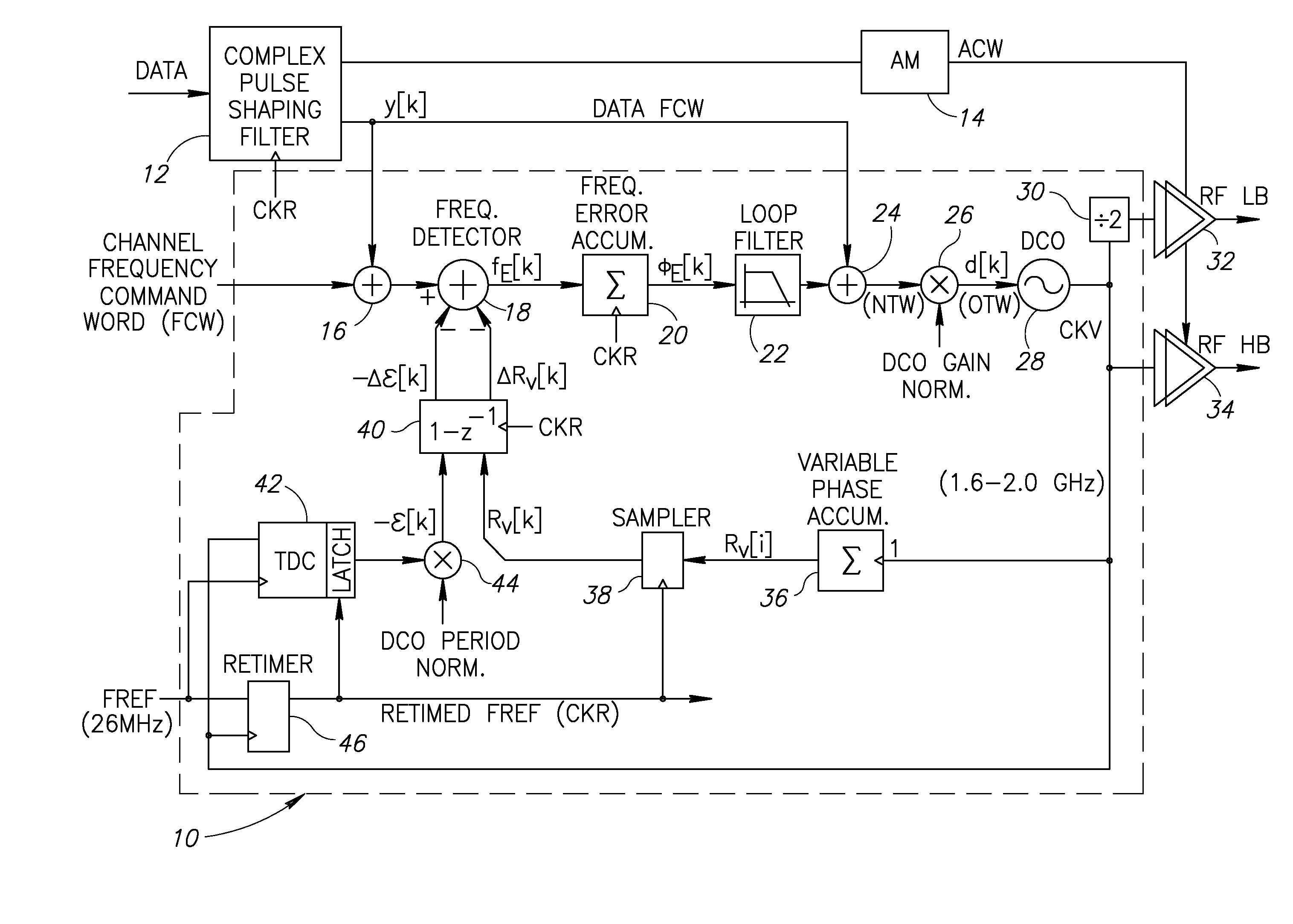
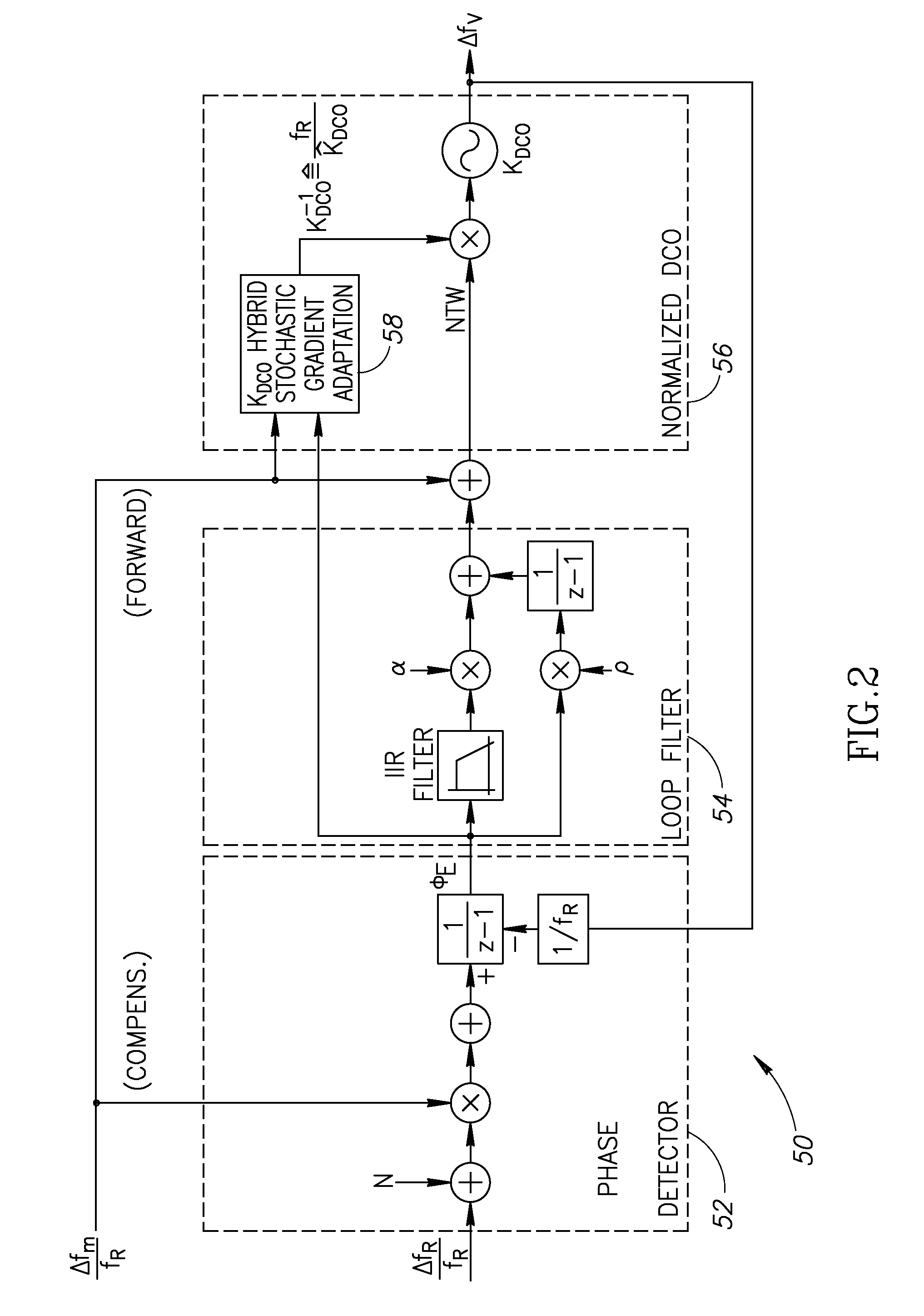
[0015]The gain calibration technique is based on an iterative hybrid stochastic gradient algorithm wherein the ADPLL phase error is sampled and correlated with the modulating data to generate a gradient. A momentum term is optionally added to provide inertia against large transients in the input data and provide tighter convergence. This process, repeated over time, results in an improved estimate of the true DCO gain that ensures optimum performance and allows continuous operation in the presence of possible sources of variability, such as temporal temperature changes during operation.
[0017]Unlike static (i.e. DC based) KDCO adaptation algorithms of the prior art, the gradient algorithm of the present invention is robust against slow center frequency drifts in the DCO due to LDO settling and variations in PVT. The hybrid stochastic gradient based KDCO adaptation algorithm of the present invention is modulation data based and is capable of tracking variations in KDCO due to temperature and other operational effects during modulation (i.e. PVT), especially in full duplex continuous transmission standards such as UMTS-FDD (WDCMA), etc.
[0018]The algorithm is operative to compute a true gradient and uses all observable samples for its updates. This results in faster and more robust convergence. For non-packetized systems, the algorithm continuously tracks the operational temperature profile while performing normal modulation.
[0020]Several advantages of the DCO gain adaptation algorithm of the present invention include (1) fast and efficient implementation; (2) low cost and complexity; (3) unlike the prior art, it does not rely on zero crossings of the phase error (which is modulation dependent); (4) exhibits robust performance for most modern modulation schemes; and (5) suitable for initial and continuous background calibration using any modulation data (not just training data).

Problems solved by technology

Unfortunately, the PLL frequency response is subject to process, voltage and temperature (PVT) variations of the charge pump, loop filter and voltage controlled oscillator (VCO).
A major disadvantage of this technique is that it is analog in nature and would require costly additional analog circuitry to implement in an all digital design.
Another disadvantage of this technique, however, is the cost of additional circuitry amounting to approximately ⅓ of the PLL, including a reference error filter, DPLL, vector test and RF phase quantizer.
Further, this technique suffers from a slow time constant of 200 ms.
Several disadvantages of this scheme are that it uses dedicated input tone signals and departs from conventional PLL operation; has limited performance; and is not particularly suited for modern non-packetized modulation schemes.
A disadvantage of this approach, however, is that it is mostly analog in nature and requires precise calibration of the oscillator and other PLL analog components.
Disadvantages of this technique, however, include its longer calibration time, dc-type algorithm, unsuitability for non-packetized operation, inability to achieve desired accuracy requirements and inability to handle DCO drift.
The prior art techniques discussed hereinabove suffer from disadvantages such as they (1) require a dedicated time for background calibration, which makes them suitable only for packetized operations, such as GSM / EDGE, but not WCDMA, (2) require dedicated and expensive analog hardware, (3) are dc based and are thus sensitive to frequency drift of the oscillator, (4) require factory calibration; (5) is unsuitable for non-packetized data; or (6) cannot meet performance requirements.

Method used


Image

  • Hybrid stochastic gradient based digitally controlled oscillator gain kdco estimation
  • Hybrid stochastic gradient based digitally controlled oscillator gain kdco estimation
  • Hybrid stochastic gradient based digitally controlled oscillator gain kdco estimation

Examples


Embodiment Construction

Notation Used ThroughoutThe fo1llowing notation is used throughout this document.TermDefinitionADPLLAll Digital Phase Locked LoopASICApplication Specific Integrated CircuitCDMACode Division Multiple AccessCKRRetimed Reference ClockCKVVariable Oscillator ClockCMOSComplementary Metal Oxide SemiconductorDCODigitally Controlled OscillatorDECTDigital Enhanced Cordless TelecommunicationsDPLLDigital Phase Locked LoopDRPDigital RF Processor or Digital Radio ProcessorEDGEEnhanced Data rates for GSM EvolutionEDREnhanced Data RateFCWFrequency Command WordFDDFrequency Division DuplexFPGAField Programmable Gate ArrayFREFFrequency ReferenceFSKFrequency Shift keyingGFSKGaussian Frequency Shift KeyingGPRSGeneral Packet Radio ServiceGSMGlobal System for Mobile communicationsHBHigh BandHDLHardware Description LanguageIEEEInstitute of Electrical and Electronic EngineersIIRInfinite Impulse ResponseLBLow BandLDOLow Drop-Out regulatorMOSCAPMetal Oxide Semiconductor CapacitorPHEPhase ErrorPLLPhase Locked ...


PUM


Abstract

A novel hybrid stochastic gradient adaptation apparatus and method for calibrating the gain of an RF or non-RF digitally controlled oscillator (DCO). The adaptation algorithm determines a true stochastic gradient between a forcing function and its corresponding system measure to estimate the system parameters being adapted. A momentum term is generated and injected into the adaptation algorithm in order to stabilize the algorithm by adding inertia against any large transient variations in the input data. In the case of adaptation of DCO gain KDCO, the algorithm determines the stochastic gradient between time varying calibration or actual modulation data and the raw phase error accumulated in an all digital phase locked loop (ADPLL). Two filters preprocess the observable data to limit the bandwidth of the computed stochastic gradient providing a trade-off between sensitivity and settling time.

Description

FIELD OF THE INVENTION[0001]The present invention relates to the field of data communications and more particularly relates to an apparatus for and the method of a hybrid stochastic gradient based gain calibration technique for a radio frequency (RF) digitally controlled oscillator (DCO) in an all digital phase locked loop (ADPLL).BACKGROUND OF THE INVENTION[0002]Oscillators are a key component in the design of radio frequency (RF) communication systems. The estimation and calibration of the modulation gain of an RF oscillator is currently an area of active research. Accurate knowledge of this gain significantly reduces the complexity and increases the performance of the transmit frequency modulation path. It is particularly beneficial in systems implemented in deep submicron CMOS and based on orthogonal frequency / phase and amplitude (i.e. polar) topology. Estimation of RF oscillator frequency-modulation gain is especially important in low-cost high-volume transceivers. In such syst...

Claims


Application Information

Patent Timeline
IPC IPC(8): H03L7/00
CPCH03L2207/50H03B5/04
Inventor WAHEED, KHURRAMSTASZEWSKI, ROBERT B.
Owner TEXAS INSTR INC
Learn More