Dual layer ceramic coating

a ceramic coating and dual layer technology, applied in the direction of coatings, metal material coating processes, chemistry apparatus and processes, etc., can solve the problems of sometimes affected durability of coatings, and achieve the effect of increasing strain tolerance and increasing durability

Inactive Publication Date: 2008-02-21
UNITED TECH CORP
View PDF8 Cites 14 Cited by
  • Summary
  • Abstract
  • Description
  • Claims
  • Application Information

AI Technical Summary

Benefits of technology

[0005]In accordance with the present invention, there is provided a dual layer ceramic coating with a structure which allows the coating to expand and contract with thermal cycles, thereby increasing strain tolerance which results in increased durability.

Problems solved by technology

However, the durability of coatings is sometimes affected due to engine operating conditions.

Method used


Image

  • Dual layer ceramic coating
  • Dual layer ceramic coating

Examples


Embodiment Construction

)

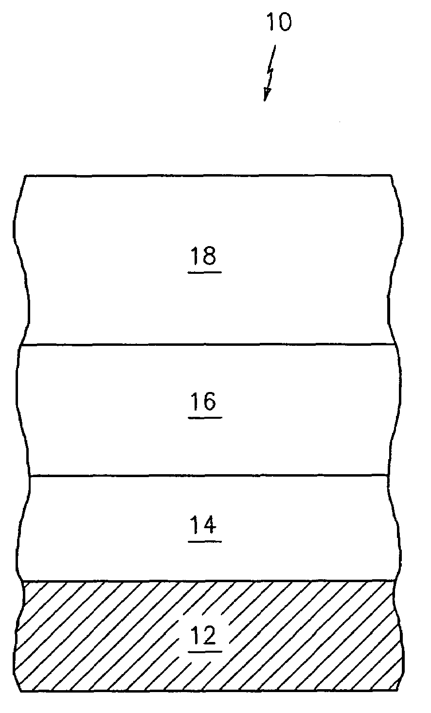
[0010]The present invention relates to a dual layer ceramic coating applied to a turbine engine component such as a blade, vane, a combustor panel or seal. The dual layer ceramic coating is capable of expanding and contracting with thermal cycles, thereby increasing strain tolerance which results in increased durability.

[0011]The turbine engine component 10 comprises a substrate 12 formed from a metallic material such as a nickel based alloy, a cobalt based alloy, a refractory metal alloy, a ceramic based or silica based alloy, or a ceramic matrix composite. A bond coat 14 is applied on top of a surface of said substrate 12. The bond coat 14 may be formed from a material selected from the group consisting of a MCrAlY, an aluminide, such as a platinum aluminide, a ceramic material, and a silica based material. The bond coat 14 may be applied using any suitable technique known in the art. Preferably, the bond coat 14 is preferably deposited using a thermal spray technique. In this te...


PUM

PropertyMeasurementUnit
thicknessaaaaaaaaaa
temperaturesaaaaaaaaaa
pressureaaaaaaaaaa

Abstract

A turbine engine component comprises a substrate, a bond coat applied to a surface of the substrate, a first ceramic layer having a cracked structure applied on top of the bond coat, and a second ceramic layer having a cracked structure applied on top of the first ceramic layer.

Description

BACKGROUND[0001](1) Field of the Invention[0002]The present invention relates to a dual layer ceramic coating applied to a turbine engine component such as a blade, a vane, a combustor panel, or a seal.[0003](2) Prior Art[0004]Thermal barrier coatings are used to provide insulation for metallic components that operate at elevated temperatures. Turbine components are typically nickel-based alloy that undergo oxidation at temperatures above 1800 degrees Fahrenheit. In order to allow high combustor and turbine operating conditions, ceramic coatings have been applied to blades, vanes, combustors, and seals. However, the durability of coatings is sometimes affected due to engine operating conditions.SUMMARY OF THE INVENTION[0005]In accordance with the present invention, there is provided a dual layer ceramic coating with a structure which allows the coating to expand and contract with thermal cycles, thereby increasing strain tolerance which results in increased durability.[0006]In accor...

Claims


Application Information

Patent Timeline
Patent Type & Authority Applications(United States)
IPC IPC(8): B32B17/06
CPCC23C4/02C23C30/00C23C4/127C23C4/105C23C4/11C23C4/134
Inventor FRELING, MELVINSCHLICHTING, KEVIN W.
Owner UNITED TECH CORP
Why Eureka
Try Eureka