A kind of anti-CMAS corrosion micro-nano composite structure thermal barrier coating and preparation method thereof
A technology of composite structure and thermal barrier coating, which is applied in the coating, metal material coating process, superimposed layer plating, etc., can solve the problems of inconsistent thermal expansion coefficient, cracks in the dense layer, and no large-scale application. Achieve the effect of good bonding force, low price, and reduce spraying cost
- Summary
- Abstract
- Description
- Claims
- Application Information
AI Technical Summary
Problems solved by technology
Method used
Image
Examples
preparation example Construction
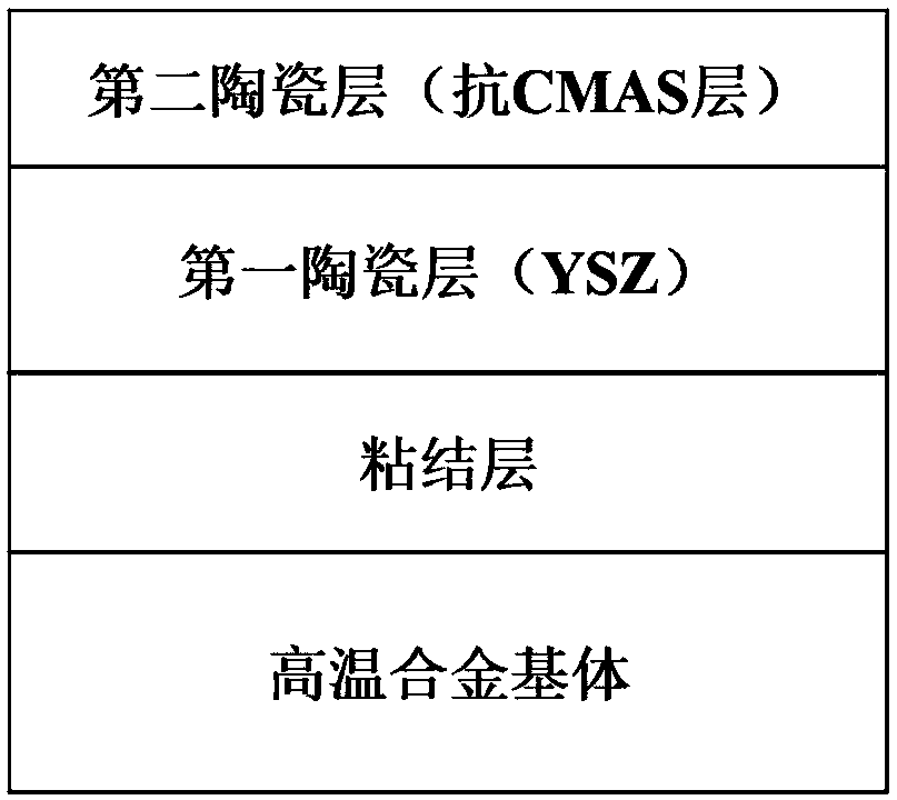
[0046] The invention provides a method for preparing a CMAS corrosion-resistant micro-nano composite structure thermal barrier coating, comprising the following steps:
[0047] The first step, substrate pretreatment;
[0048] The surface of the superalloy substrate is polished on 200#, 400#, 600#, 800# sandpaper in turn, then ultrasonically cleaned for 10 minutes, and sandblasting pretreatment to make the surface roughness Ra<2. The high temperature alloy matrix is K3 alloy.
[0049] The second step is to prepare NiAlX (X selects Dy, Hf or Zr, etc.), NiCoCrAlY or NiAlPt bonding layer on the substrate.
[0050] (A) NiAlX (X selects Dy, Hf or Zr, etc.) or NiCoCrAlY bonding layer prepared by low-pressure plasma spraying method;
[0051] Install the substrate pretreated in the first step in the fixture of the low-pressure plasma spraying equipment, and then install it on the automatic workpiece moving table in the vacuum chamber, and adjust the main process parameters: the cur...
Embodiment 1
[0080]Embodiment 1: Preparation on the surface of the superalloy substrate: low-pressure plasma spraying NiCoCrAlY bonding layer+plasma evaporation deposition of the first ceramic layer YSZ+plasma evaporation deposition of the thermal barrier coating of the second ceramic layer YSZ, the specific steps are as follows:
[0081] In the first step, the surface of the superalloy substrate is polished on 200#, 400#, 600#, and 800# sandpaper in sequence, then ultrasonically cleaned for 10 minutes, and pretreated by sandblasting to make the surface roughness Ra<2. The high temperature alloy is K3 alloy.
[0082] In the second step, a NiCoCrAlY bonding layer is prepared on the substrate by low-pressure plasma spraying.
[0083] Install the alloy substrate in the fixture of the low-pressure plasma spraying equipment, and then install it on the automatic workpiece moving table in the vacuum chamber, adjust the main process parameters: the current is 600A, the voltage is 40kw, the powder ...
Embodiment 2
[0095] Embodiment 2: Preparation on the surface of the superalloy substrate: electron beam physical vapor deposition NiAlDy bonding layer+electron beam physical vapor deposition first ceramic layer YSZ+plasma evaporation deposition thermal barrier coating of the second ceramic layer YSZ, the specific steps are as follows:
[0096] In the first step, the surface of the superalloy substrate is polished on 200#, 400#, 600#, and 800# sandpaper in sequence, then ultrasonically cleaned for 10 minutes, and pretreated by sandblasting to make the surface roughness Ra<2. The high temperature alloy is K3 alloy.
[0097] In the second step, an electron beam physical vapor deposition method is used to prepare a NiAlDy bonding layer on the substrate, and the preparation steps are as follows:
[0098] (1) Use high-purity nickel (Ni), high-purity aluminum (Al) and dysprosium (Dy) with a purity of 99.7wt.%. According to the design distribution ratio, the Al content is 50mol%, the Dy content is...
PUM
| Property | Measurement | Unit |
|---|---|---|
| particle diameter | aaaaa | aaaaa |
| particle diameter | aaaaa | aaaaa |
| particle diameter | aaaaa | aaaaa |
Abstract
Description
Claims
Application Information
 - R&D
- Intellectual Property
- Life Sciences
- Materials
- Tech Scout
- Unparalleled Data Quality
- Higher Quality Content
- 60% Fewer Hallucinations
Browse by: Latest US Patents, China's latest patents, Technical Efficacy Thesaurus, Application Domain, Technology Topic, Popular Technical Reports.
© 2025 PatSnap. All rights reserved.Legal|Privacy policy|Modern Slavery Act Transparency Statement|Sitemap|About US| Contact US: help@patsnap.com


