Device and method for single-needle in vivo electroporation

a single-needle, in vivo technology, applied in the direction of internal electrodes, skin piercing electrodes, therapy, etc., can solve the problems of cumbersome use of such multiple-needle devices, difficult control, variability in the electroporation of cells within the treatment zone, etc., to achieve the effect of lessening the sensation of electric stimulus

Inactive Publication Date: 2008-02-21
GENETRONICS INC
View PDF11 Cites 96 Cited by
  • Summary
  • Abstract
  • Description
  • Claims
  • Application Information

AI Technical Summary

Benefits of technology

[0008] In a second embodiment, the invention provides for any number of structural arrangements of the anode(s) and cathode(s) on the single-needle electrode such that there are at least two electrically opposite electrically conductive leads (i.e., at least one anode and at least one cathode) situated in association with a single elongate shaft, which shaft itself is constructed to be electrically inert. In one embodiment said single-needle electrode can comprise anode(s) and cathode(s) and an electrically inert material, such as a medically acceptable plastic or polycarbonate, filling the space between the anode(s) and cathode(s) or an electrically inert coating on an elongate rigid material that itself is electrically conductive, such as a metallic hypodermic needle. In a preferred embodiment the shaft upon which the anode(s) and cathode(s) are situated can have cross sectional dimensions of between 0.05 mm to a 1.5 mm. In a related embodiment the single-needle electrode can comprise a combination of opposing elongate tissue piercing anode and a cathode spaced and electrically insulated from one another but with no inert material there between. In such an embodiment the spaced anode and cathode run parallel to one another each having a distal and a proximal end and positioned relative to one another such that the distal ends lie opposite one another and the proximate ends are held one to another by an electrically inert substrate. In either embodiment, the anode(s) and cathode(s) of the tissue penetrating single-needle electrode can be spaced between 0.05 mm and 1.5 mm. In a related embodiment, the electrodes themselves can have a length exposed along the elongate shaft anywhere from the whole single-needle electrode length to only a portion of the single-needle shaft, such as near the shaft penetration tip. In another embodiment, the electrodes can have cross sectional dimensions of between 0.005 and 0.80 mm. In yet another structural arrangement embodiment, the single-needle electrode can comprise a hypodermic needle comprising at least two elongate electrodes spaced along at least a portion of the length of the hypodermic needle exterior. For example, the hypodermic needle can include at least two electrodes (i.e., an anode and a cathode) running along a portion of the length of the needle. (See FIG. 10A) In other examples, multiple electrodes can be formed on the exterior of a hypodermic injection needle such as disclosed in FIGS.

Problems solved by technology

For example, use of many needles and high electric field (voltages) causes more pain while high injection volume makes dosing difficult to control as it causes waste of the drug (most of the drug is not getting into the cells as it will be outside the treatment zone).
Also, use of such multiple needle devices is cumbersome and a cause for apprehension from the standpoint of the patient.
Besides the invasive aspect of a device with multiple n

Method used


Image

  • Device and method for single-needle in vivo electroporation
  • Device and method for single-needle in vivo electroporation
  • Device and method for single-needle in vivo electroporation

Examples


examples

[0057] The following examples are given to illustrate various embodiments which have been made of the present invention. It is to be understood that the following examples are not comprehensive or exhaustive of the many types of embodiments which can be prepared in accordance with the present invention.

example i

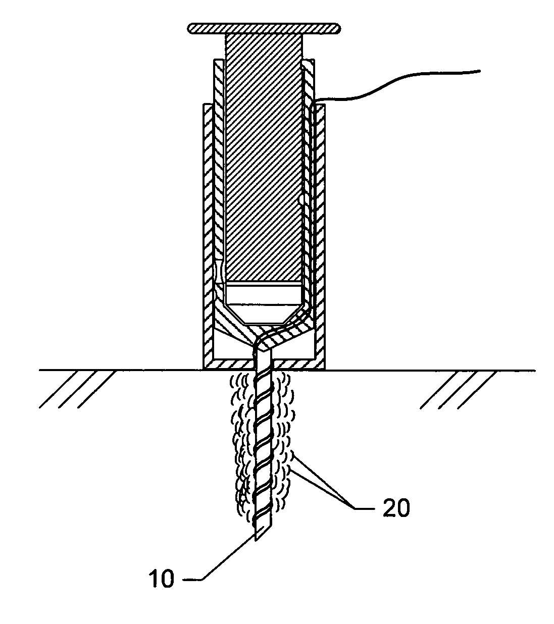
[0058] Turning now to various aspects of the invention, the device can comprise molecule delivery reservoir 20 and single-needle electrode 10 components as shown, for example, in (FIG. 5). Additional embodiments include sharps cover 11, resilient membrane 12 sealing a portion of the structure comprising the reservoir 20 for uses in filling the reservoir (such as by piercing of a syringe needle), and mechanisms such as dimples 13 and recesses 14 and 14* in the reservoir 20 housing structure for keeping the sharps cover 11 in a semi-fixed position of either open / retracted (FIG. 5C), or closed / covered (FIGS. 5A and B). Further embodiments include mechanisms for keeping the plunger 9 in a semi-fixed open / retracted or a closed / expelled position, such as, for example, dimples 15 and recesses 16 and 16*. It should be clear to one of skill in the art that regardless of the method employed to provide for semi-fixed positioning of the sharps cover 11 and plunger 9, such positioning can easily...

example ii

[0064] In this example, results are depicted for delivering molecules by reversible poration to cells situated along and near the track formed by the insertion of the invention single-needle electrode into a tissue.

[0065] As depicted in FIGS. 11A and B, rabbit quadriceps muscle was injected with DNA encoding beta-galactosidase in a bolus comprising 0.2 ml and DNA concentration of 1 mg / ml. The electrodes were pulsed using 2 pulses of 250 mAmps, 20 millisec duration. Following electroporation, the beta-galactosidase gene was expressed in cells affected by the electroporation. At day 4 after electroporation, the rabbits were sacrificed and the muscles were prepared in 3 mm thick slices through the site on insertion of the single-needle electrode. Following chemical fixation, the beta galactosidase expressing cells in the muscle slices where visualized by an enzymatic reaction. The arrows in FIG. 11A depict the direction of the insertion of the electrode into the rabbit muscle. As show...


PUM


Abstract

Described is a device and method for administration of molecules to tissue in vivo for various medical applications, the device comprising a single-needle electrode which provides for the ability, when the needle is inserted into tissue, such as skin or muscle, to pulse tissue with a non-uniform electric field sufficient to cause reversible poration of cells lying along or in close proximity to the track made by the needle upon its insertion into said tissue

Description

RELATED APPLICATIONS [0001] This application is a continuation-in-part of U.S. patent application Ser. No. 11 / 704,591, filed Feb. 9, 2007, and claims priority to Provisional U.S. patent application 60 / 772,255 filed Feb. 11, 06.FIELD OF THE INVENTION [0002] This invention relates to electroporation of cells in vivo, particularly cells of a patient's tissues. More specifically, this invention relates to novel devices and methods for delivering molecules to cells situated at, near and / or adjacent to a predetermined insertion track site of an elongate single-needle electrode. Still more specifically, the invention concerns the electroporated delivery of substances into cells along and in the vicinity of the needle track made by insertion of the electrode from the surface of a tissue and into the tissue to a depth of from about 3 millimeters to about 3 cm, which tissues can comprise any tissues, including without limitation skin, epidermis, dermis, hypodermis, connective tissue, striated...

Claims


Application Information

Patent Timeline
IPC IPC(8): A61N1/30
CPCA61N1/327A61N1/0502
Inventor KJEKEN, RUNEMATHIESEN, IACOBTJELLE, ELISABETH TORUNNMCHUGH, GEORGE
Owner GENETRONICS INC
Why Eureka
Try Eureka