
Data processor

a data processor and data technology, applied in the field of data processors, can solve the problems that the cpu (central processing unit) taking no measures against overflow may fall into undesirable operation stop, and achieve the effect of free, smooth and efficient restoration from interrupts and excellent applicability to multitask processing

Inactive Publication Date: 2008-02-21
RENESAS TECH CORP
View PDF8 Cites 14 Cited by
  • Summary
  • Abstract
  • Description
  • Claims
  • Application Information

AI Technical Summary

Benefits of technology

[0006] The present invention provides a technique for preventing a data processor from malfunctioning on saving and restoring register banks.
[0007] An object of the present invention is to provide a data processor that is free from undesirable operation stop due to an overflow of register banks.
[0008] Another object of the present invention is to provide a data processor that can smoothly and efficiently perform restoration from interrupts, whether task switching is involved or not, and is excellent in applicability to multitask processing.
[0017] This helps to prevent the data processor from undesirable operation stop due to an overflow of the register banks.
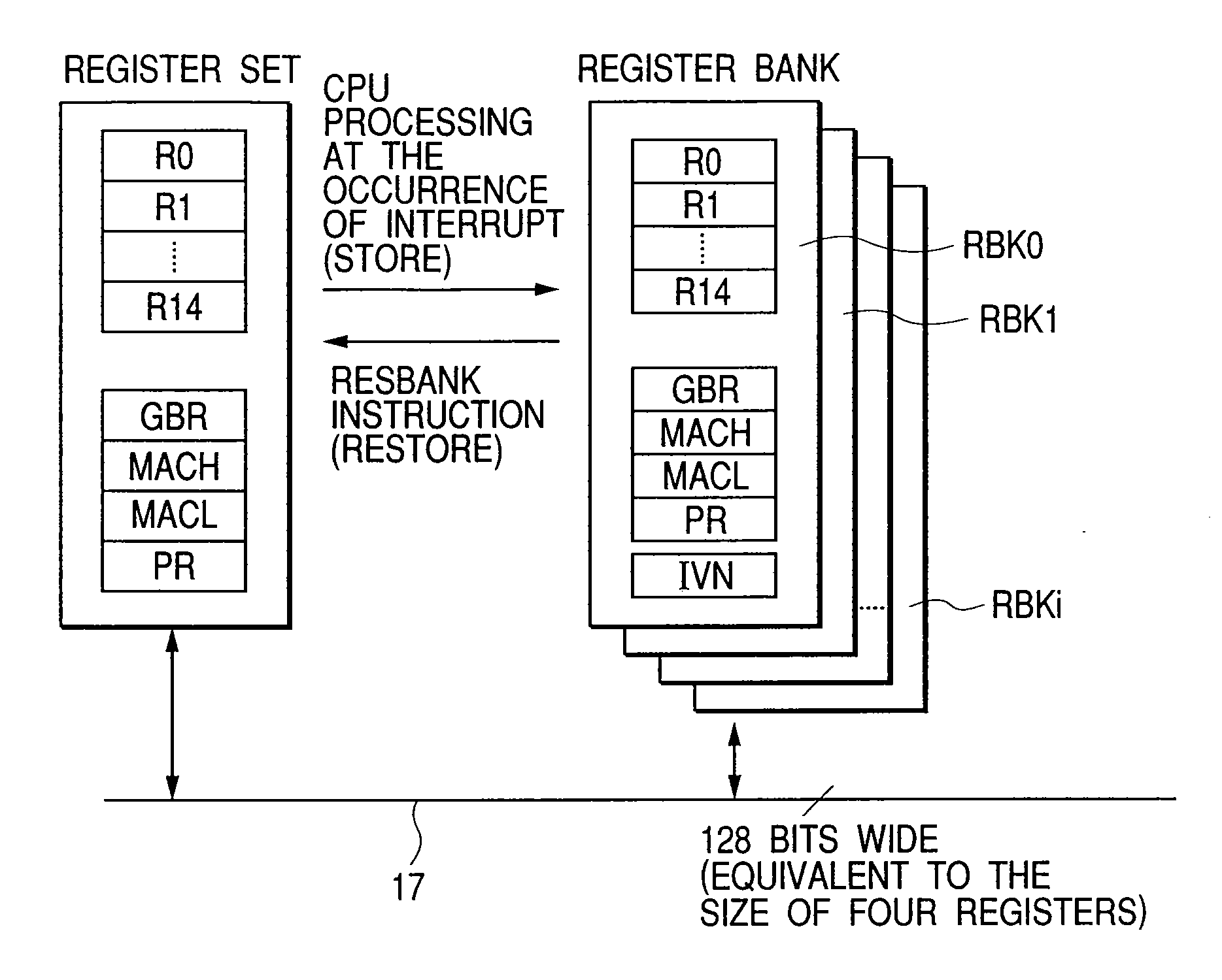
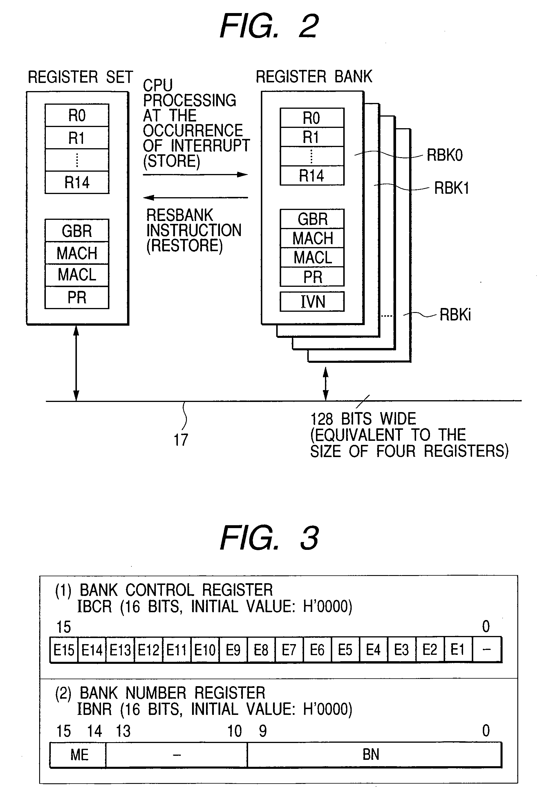
[0019] The plural register banks are constituted by a RAM, a dedicated bus is used for connection between the RAM and a predetermined register set, and the bus is given as many bits as parallel data transfer is allowed in units of plural registers contained in the register set. Interrupt exception handling can be performed in parallel with save processing for the register set through the dedicated bus, resulting in a higher interrupt response speed. In short, concurrent saving of plural registers contributes to reduction in interrupt service time (interrupt response performance and interrupt restore performance). By connecting the bank area over the dedicated bus to perform parallel processing, apparent overhead of register save and restore processing can be reduced.

Problems solved by technology

As a result, a CPU (central processing unit) taking no measures against overflow may fall into undesirable operation stop.

Method used


Image

  • Data processor
  • Data processor
  • Data processor

Examples


Embodiment Construction

>

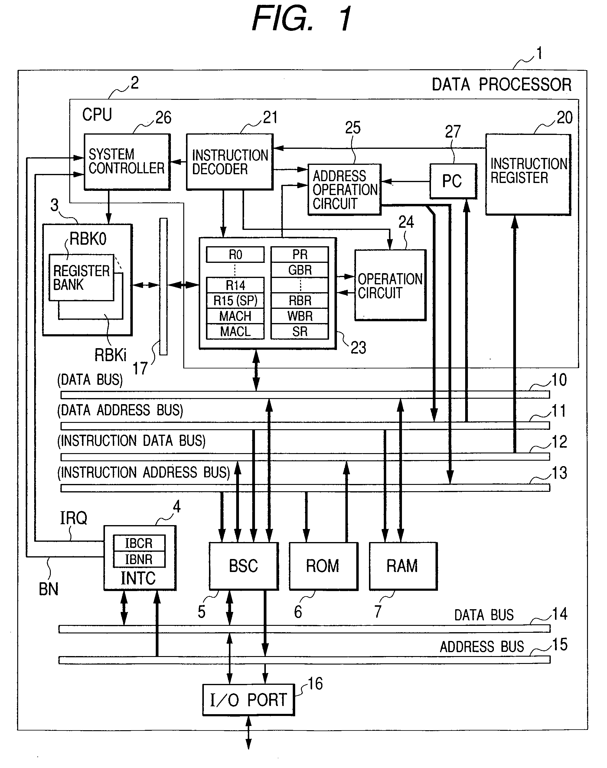
[0035]FIG. 1 is a block diagram showing a data processor according to an embodiment of the present invention. A data processor 1 shown in the figure is formed on a single semiconductor board (semiconductor chip) such as a single-crystal silicon by, e.g., CMOS integrated circuit manufacturing technology.

[0036] The data processor 1 shown in the figure comprises: a CPU 2; a bank memory 3; an interrupt controller (INTC) 4; a bus state controller (BSC) 5; a ROM (read only memory) 6; and a RAM 7.

[0037] The CPU 2 is connected to the RAM 7 over a data bus 10 and a data address bus 11, and to the ROM 6 over an instruction data bus 12 and an instruction address bus 13. The RAM 7 is used as a work area or data temporary storage area of the CPU 2. The ROM 6 stores operation programs of the CPU 2 such as OS and control programs. The buses 10 to 13 are interfaced via the bus state controller 5 to a peripheral data bus 14 and a peripheral address bus 15, where external input-output circuits suc...


PUM


Abstract

The present invention prevents a data processor from undesirable operation stop due to an overflow of a plurality of register banks. A status register includes an overflow flag to indicate an overflow of the plurality of register banks. When an interrupt exception occurs in a state in which data has been saved to all banks of the register banks, and the accepted interrupt exception is permitted to use the register banks, a central processing unit saves data of a register set to a stack area and reflects an overflow state in the overflow flag. When the overflow flag indicates an overflow state, if data restoration from the register banks to the register set is directed, the central processing unit restores the data from the stack area to the register set.

Description

BACKGROUND OF THE INVENTION [0001] The present invention relates to a data processor including register banks, more particularly to register set saving and restoring involved in interrupt exception (refers to both interrupts and exceptions) handling and task switching, and a technique effectively applied to, e.g., single chip microcomputers. [0002] When interrupt exception handling or task switching under multitask environments is performed, a predetermined register set such as general purpose registers, a status register, and the like at that time is saved to enable restoration to a previous state. Although a stack area allocated to an external memory and the like can be used as a save destination, register banks can be used to rapidly save and restore the register set. Use of the register bank method shortens interrupt response time. [0003] Patent Publication 1 describes a single-chip microcomputer including general purpose registers of bank structure by use of an internal RAM (ra...

Claims


Application Information

Patent Timeline
Patent Type & Authority Applications(United States)
IPC IPC(8): G06F9/30G06F9/46G06F9/00G06F9/312G06F9/48
CPCG06F9/30043G06F9/30123G06F9/3012
Inventor SUGURE, YASUOISHIKURA, TOMOMIHIRAYANAGI, KAZUYAKATAOKA, TAKESHITAKEUCHI, SEIJIYAMADA, HIROMICHIYAMAZAKI, TAKANAGA
Owner RENESAS TECH CORP
Learn More