Oxygen concentration system and method

a technology of oxygen concentration system and oxygen concentrator, which is applied in the direction of filtration separation, auxillary pretreatment, separation process, etc., can solve the problems of not meeting the demands of many patients, affecting the efficiency and cost of these systems, and the desire for high efficiency

Active Publication Date: 2008-02-28
PHILIPS RS NORTH AMERICA LLC
View PDF14 Cites 29 Cited by
  • Summary
  • Abstract
  • Description
  • Claims
  • Application Information

AI Technical Summary

Benefits of technology

[0020]These and other objects, features, and characteristics of the present invention, as well as the methods of operation and functions of the related elements of structure and the combination of parts and economies of manufacture, will become more apparent upon consideration of the following description and the appended claims with reference to the accompanying drawings, all of which form a part of this specification, where

Problems solved by technology

Such structures require extensive valving and plumbing which affects the efficiency and costs of these systems.
While many conventional systems are capable of delivering sufficient flow rates to meet the patient's need, they do not meet many of the patients' demands including the desire for high efficiency, high product gas concentrations, and low weight.
For example, many of the conventional systems require a significant amount of molecular sieve materials and power to operate.
The restricted quantity of ambient air reduces the load on the compressor and thus the power consumed by the system.
While the systems of the prior art are s

Method used


Image

  • Oxygen concentration system and method
  • Oxygen concentration system and method
  • Oxygen concentration system and method

Examples


Embodiment Construction

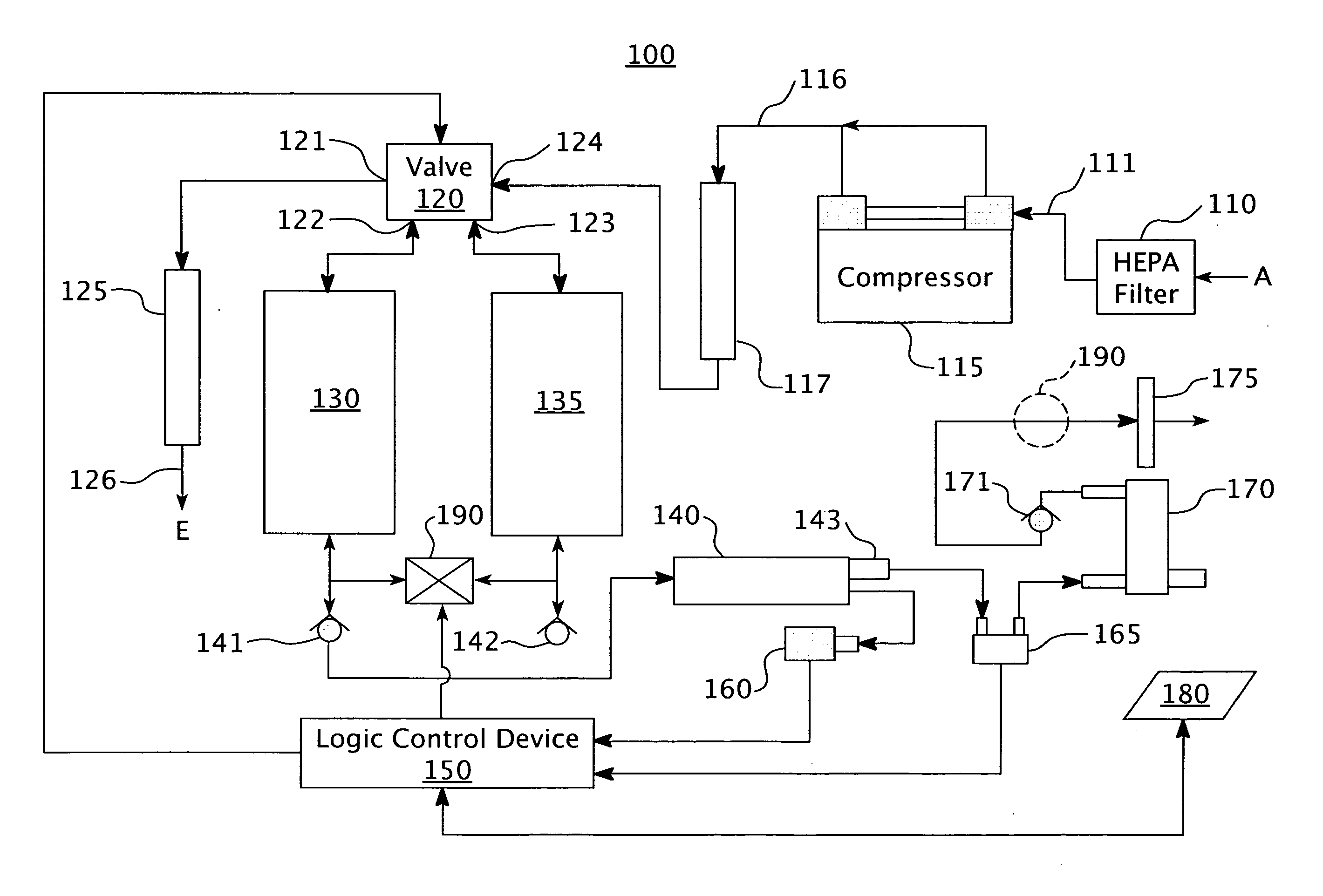
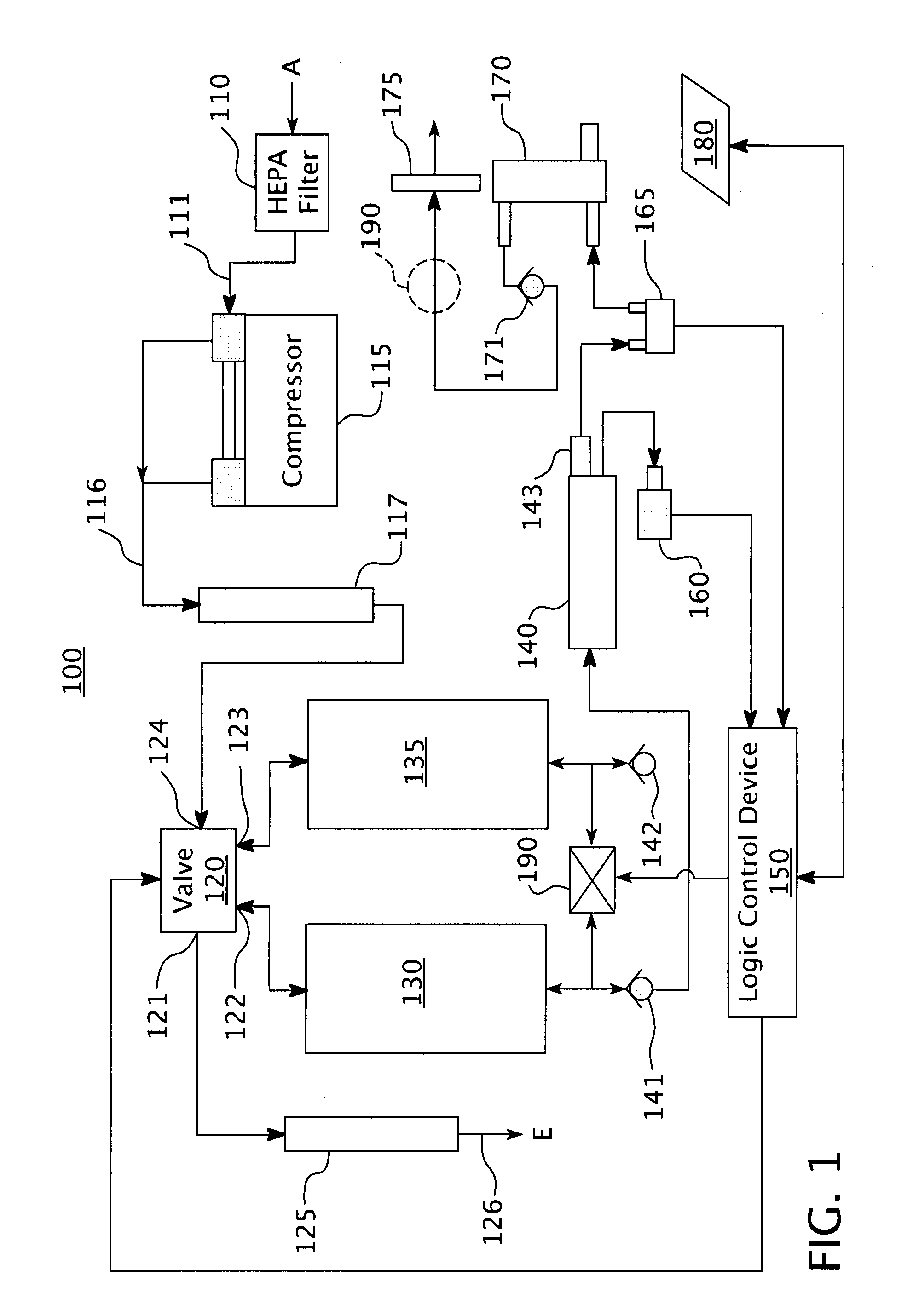
[0043]Referring now in detail to the drawing figures, wherein like reference numerals represent like parts throughout the several views. FIG. 1 illustrates a schematic (block) diagram of a pressure swing adsorption system 100 in accordance with an embodiment of the present invention. Pressure swing adsorption system 100 includes some standard components that are known to those in the art. The operation and design of the conventional aspects of pressure swing adsorption system 100 are described in U.S. Pat. Nos. 5,183,483 and 5,997,617, both of which are hereby incorporated by reference. Those of skill in the art will appreciate that while the disclosure herein may focus on the pressure swing adsorption systems for the generation of oxygen, the embodiments of the present invention incorporate and apply to many different types of pressure swing adsorption systems.

[0044]The terms “molecular sieve chamber”, “sieve chamber”, and “sieve bed” are used synonymously herein to refer to device...


PUM

PropertyMeasurementUnit
Fractionaaaaaaaaaa
Fractionaaaaaaaaaa
Fractionaaaaaaaaaa

Abstract

The present system is an adsorption system for separating air into a concentrated gas component, which has an air supply, a compressor for receiving and compressing the air supply, providing a compressed air supply, and molecular sieve material for separating the compressed air supply into a concentrated gas component. The adsorption system delivers at least 5 liters per minute (LPM) of concentrated gas component from the molecular sieve material in which the system has a specific total weight per LPM <9 lbs/LPM. Additionally, an output quantity of the concentrated gas is delivered by the adsorption system and a purging quantity of the concentrated gas is dispensed into a sieve chamber of the adsorption system undergoing a purge cycle. The purging quantity has a value equal to or less than the difference between the maximum quantity and the output quantity, and the purging quantity is controlled based on the output quantity.

Description

CROSS-REFERENCE TO RELATED APPLICATIONS[0001]This application claims priority under 35 U.S.C. § 119(e) from provisional U.S. patent application No. 60 / 840,523, filed Aug. 28, 2006, the contents of which are incorporated herein by reference.BACKGROUND OF THE INVENTION[0002]1. Field of the Invention[0003]This invention relates to a pressure swing adsorption system, and, more particularly, to an oxygen concentrator system and method of operating same having a multi-chamber canister for receiving compressed air from a compressor and directing the air through a series of chambers integral within a single assembly for producing concentrated oxygen in a pressure swing adsorption system.[0004]2. Description of Related Art[0005]Adsorption separation processes depend on the ability of certain solids to selectively adsorb one or more components from a gaseous mixture. In oxygen concentrators for patient use, the adsorption separation processes are usually fixed bed operations, including two ma...

Claims


Application Information

Patent Timeline
IPC IPC(8): B01D46/46B01D50/00
CPCA62B21/00B01D53/0415B01D53/047B01D53/0476B01D2253/108B01D53/0454B01D2257/102B01D2259/402B01D2259/4533B01D2259/455A61M16/101B01D2256/12A61M16/107
Inventor DOLENSKY, JOSEPH T.
Owner PHILIPS RS NORTH AMERICA LLC
Why Eureka
Try Eureka