
Exposure device for the production of screen print stencils

a technology of exposure device and screenprint stencil, which is applied in the direction of optical devices, photomechanical devices, instruments, etc., can solve the problems of severely limiting the “image production speed” of screenprint stencils, and setting limits for dmds, etc., to achieve less expensive, easy maintenance, and less effort

Inactive Publication Date: 2008-02-28
XPOSE HLDG
View PDF5 Cites 32 Cited by
  • Summary
  • Abstract
  • Description
  • Claims
  • Application Information

AI Technical Summary

Benefits of technology

[0009] The use of laser diodes that can be modulated directly has various significant advantages. For one thing, the need for continuous operation is eliminated, and thus, the power loss of the entire exposure device can be significantly reduced. Furthermore, there are almost no upper limits on the reaction speed of laser diodes (at least in the area of application that is of interest here, that of exposing screen-print stencils), because the limit values that can be reached lie in the GHz range. Furthermore, because the laser diodes are easy to control, and there are no light-deflecting mirrors in the beam path, another case of undesirable power loss is eliminated, specifically because no additional losses have to be accepted, with the exception of absorption losses in the materials in the beam path (lens system components).
[0018] The new machine concept therefore has very significant advantages as compared with the current machine concepts, particularly with regard to convertibility, ease of maintenance, and expandability.

Problems solved by technology

Despite the current widespread use of DMD modules (for example for beamers), however, the device according to European Patent No. 0 953 877 has some important disadvantages.
Since the DMDs are mechanically moved mirror systems, there are, of course, certain limits with regard to changes in the beam of light to be modulated that take place very quickly.
Common DMDs have a limit frequency of about 20 kHz, which, of course, severely limits the “image production speed” for the screen-print stencils.
Here again, limits are set for the use of DMDs, because relatively high losses always occur due to the use of mirrors (the “reflected-away” parts of the beam of light manifest themselves in the form of relatively great heat loss, which must be carried away).
Finally, a continuous radiation source that works with high power must be used as the light source, and this again is expensive and related to relatively great power losses (because only part of the energy supplied is actually converted to usable radiation).

Method used


Image

  • Exposure device for the production of screen print stencils
  • Exposure device for the production of screen print stencils

Examples


Embodiment Construction

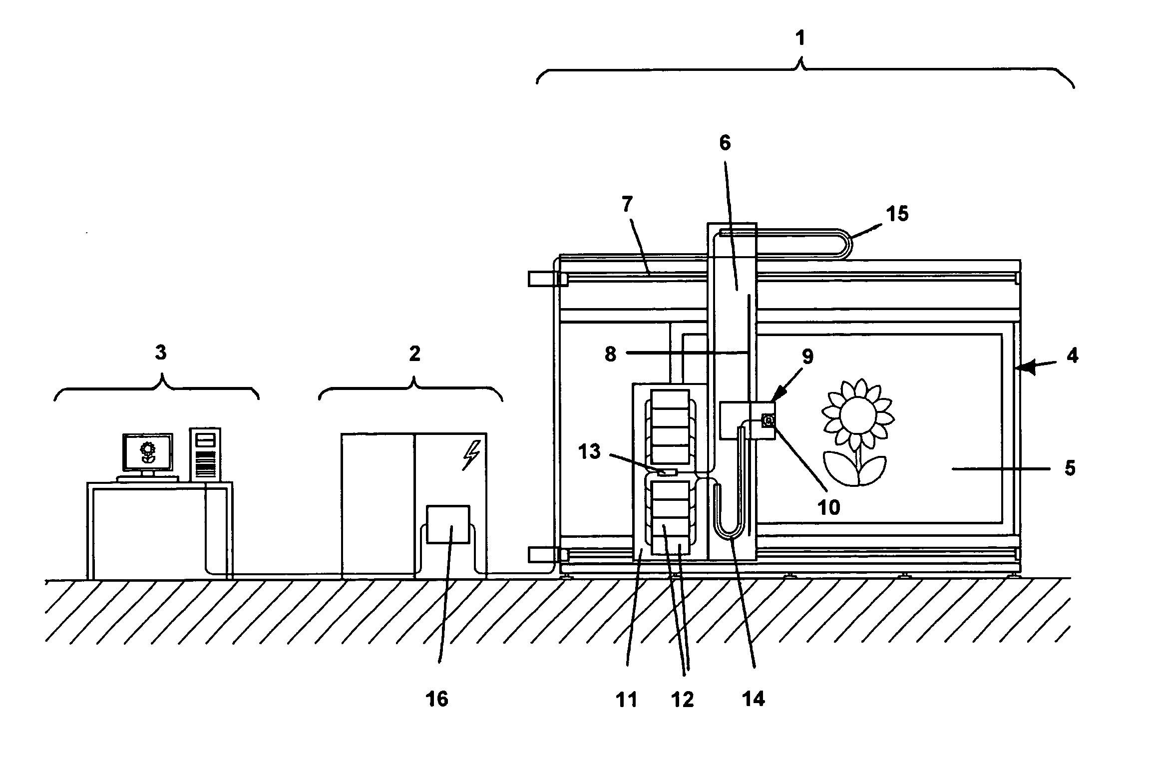
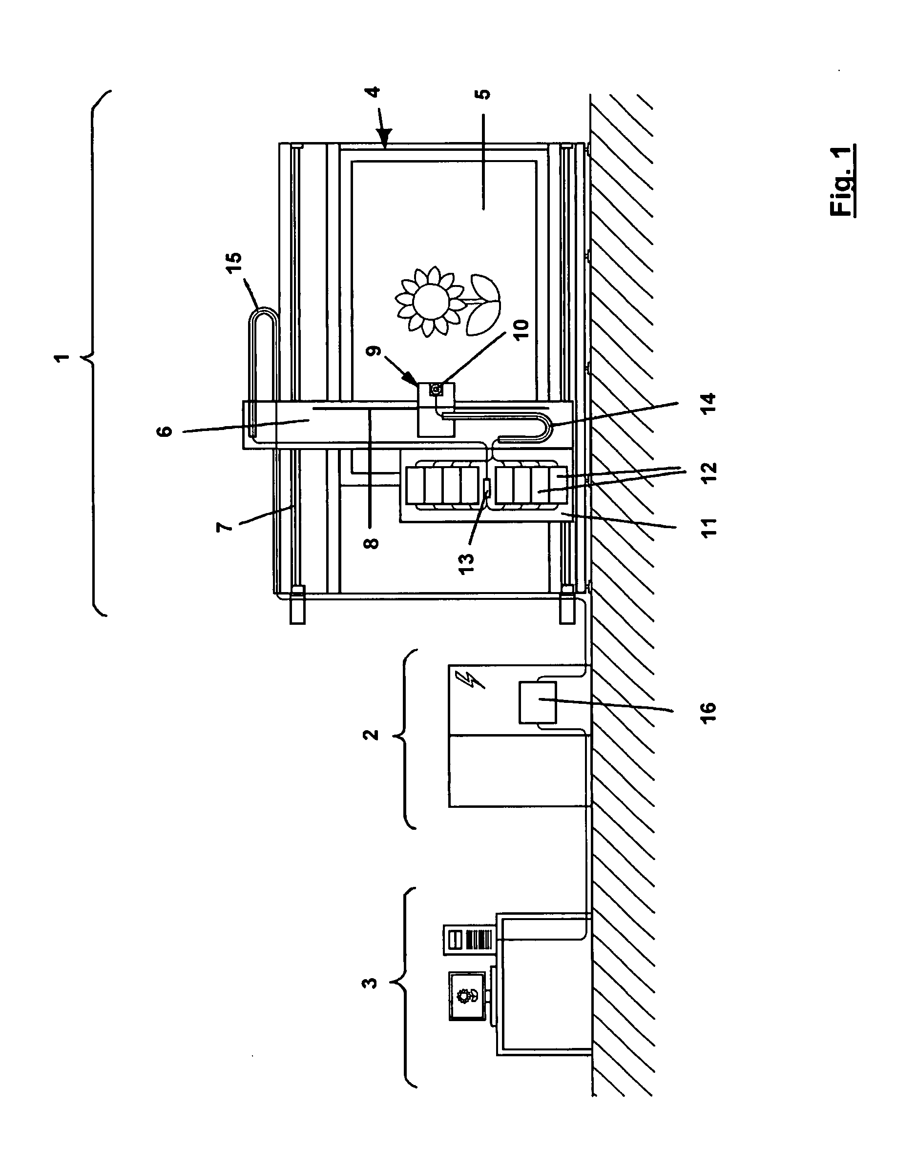
[0022] An exposure device for the production of screen-print stencils is structured using the portal construction method and consists essentially of an exposure unit 1, a control unit 2, and a computer unit 3.

[0023] Exposure unit 1 comprises a vertically disposed processing table having a holder 4 for screen-print stencils 5 (to be exposed). A portal arm 6 can be moved on an X axis guide 7, in an X direction, above holder 4 and the screen-print stencil. An exposure head 9 having a focusing lens system 10 with an auto-focusing device 19 can be moved in a Y direction on portal arm 6, on a Y axis guide 8. The X direction therefore corresponds to the movement direction of portal arm 6. Precision guides and precision drives (not shown) are present both for the movement in the X direction and for the movement in the Y direction.

[0024] An interface part 11 is attached to portal arm 6. Several modules 12 that conduct heat away are situated on interface part 11; they have groups of laser d...


PUM

PropertyMeasurementUnit
wavelength rangeaaaaaaaaaa
frequencyaaaaaaaaaa
poweraaaaaaaaaa

Abstract

An exposure device for the production of screen-print stencils has a holder for the stencil, an exposure system with a light source, and a lens system in an exposure head that is movable. A signal source that yields digital signals is connected with the exposure system. The light source is a number n of laser diodes that work in the wavelength range of 300-450 nm. Several modules comprising groups of laser diodes are present on the exposure unit and can be controlled by the signals of the signal source. The light signals of the laser diodes are guided to a raster plate in the exposure head, by light-guiding fibers. The light output of the raster plate is passed to a focusing lens system in the exposure head, which is adapted to the laser diodes in terms of the wavelength range.

Description

BACKGROUND OF THE INVENTION [0001] 1. Field of the Invention [0002] The invention relates to an exposure device for the production of screen-print stencils. The invention particularly relates to an exposure device for the production of screen-print stencils, having a holder for the screen-print stencil, an exposure system that has at least one light source that produces a beam of light, and a lens system, in an exposure head. There is a signal source that yields digital signals, which is connected with the exposure system in such a manner that the entire screen-print stencil can be exposed in accordance with the signals. The exposure head can be moved relative to the screen-print stencil. This is therefore a device for implementing a so-called cts (computer-to-screen) method, in other words a device in which the data to be transferred to the artwork (screen-print stencils) are controlled by the digital signals of a computer, and made available by way of an optical exposure system. [...

Claims


Application Information

Patent Timeline
Patent Type & Authority Applications(United States)
IPC IPC(8): G03F7/12B41C1/14
CPCG03F7/12G03F7/24G03F7/2053G03F7/2055
Inventor BERNER, PETER
Owner XPOSE HLDG
Features
  • Generate Ideas
  • Intellectual Property
  • Life Sciences
  • Materials
  • Tech Scout
  • Unparalleled Data Quality
  • Higher Quality Content
  • 60% Fewer Hallucinations
Learn More