Cooling device for an electrical operating means

a cooling device and operating means technology, applied in the direction of electrical apparatus construction details, indirect heat exchangers, light and heating apparatus, etc., can solve the problems of limited cooling effect which can be achieved, inability to ensure reliable continuous operation, and inability to always maintain heat conduction properties. stable and stable construction of contact walls

Inactive Publication Date: 2008-02-28
ABB RES LTD
View PDF18 Cites 17 Cited by
  • Summary
  • Abstract
  • Description
  • Claims
  • Application Information

AI Technical Summary

Benefits of technology

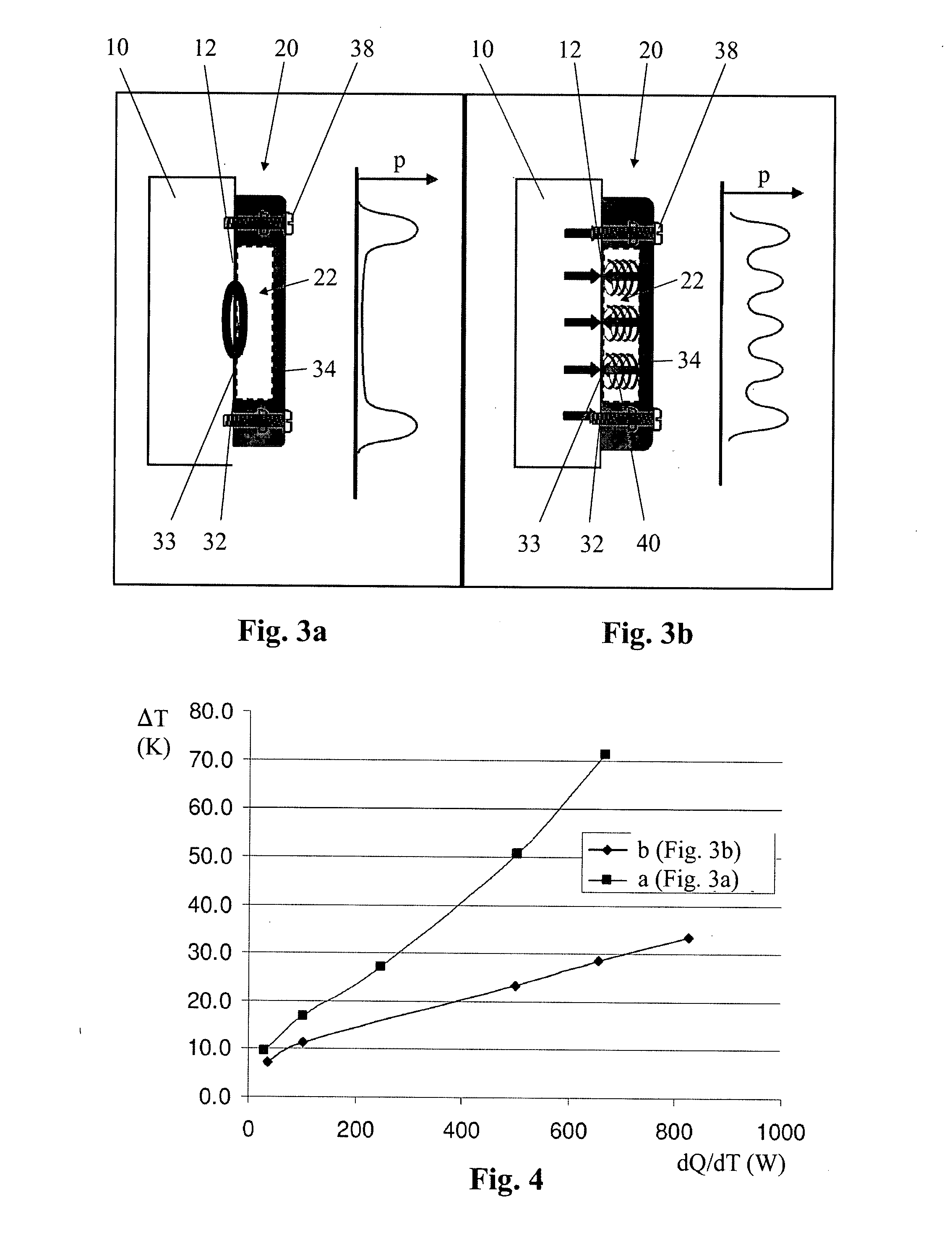
[0007]Owing to the contact pressure, a force-fitting connection can be achieved between at least part of the contact face and the surface to be cooled. Owing to the force-fitting connection, good thermal contact which is stable over long time periods can be achieved between the contact face and the surface to be cooled even in the presence of manufacturing tolerances or of other surface irregularities. The contact-pressure means makes it possible to design the contact wall to be thin and therefore particularly thermally conductive and nevertheless for it to bear against the surface to be cooled.
[0011]In embodiments, the contact-pressure means is arranged in order to transfer a counterpressure to the contact pressure onto the peripheral wall. As a result, a compact and stable construction is possible. In particular embodiments, the counterpressure to the contact pressure is transferred onto one wall of the peripheral wall which is opposite the contact wall.
[0014]In embodiments, the cooling device is a passive cooling device, for example a heat pipe or a heat siphon. In some of these embodiments, the peripheral wall forms an evaporator for evaporating the coolant, and the cooling device further comprises a condenser for condensing the coolant, which condenser is connected to the evaporator and has an apparatus for emitting heat to the surrounding environment, for example a cooling rib arrangement. These embodiments have the advantage that an efficient cooling effect can be brought about without any or with little energy consumption.
[0016]In embodiments, the coolant is contained in the volume defined by the interior of the peripheral wall. In embodiments, the interior of the peripheral wall is sealed off in a gas-tight manner from the surrounding environment or from the ambient air. It is therefore possible to prevent the coolant from entering the surrounding environment and therefore to prevent the cooling effect from being reduced. A possibly environmentally harmful effect of the coolant is also reduced.
[0018]In embodiments, the contact wall has a base material and a coating. The base material may contain, for example, copper, aluminum or steel. The coating is generally arranged on the side of the contact face. The coating is generally softer than the base material, i.e. it has a lower Brinell hardness than the base material. The coating may contain silver. The coating has the advantage that it can compensate for small irregularities of the contact face or of the surface to be cooled and that, nevertheless, a stable construction of the contact wall consisting of a suitable material is possible.

Problems solved by technology

For example, the connection does not always have optimum heat conduction properties and therefore limits the cooling effect which can be achieved.
Also, the heat conduction properties are not always stable during long-term operation.
Therefore, reliable continuous operation can only be ensured with regular complex diagnosis and possible maintenance of this connection.

Method used


Image

  • Cooling device for an electrical operating means
  • Cooling device for an electrical operating means
  • Cooling device for an electrical operating means

Examples


Embodiment Construction

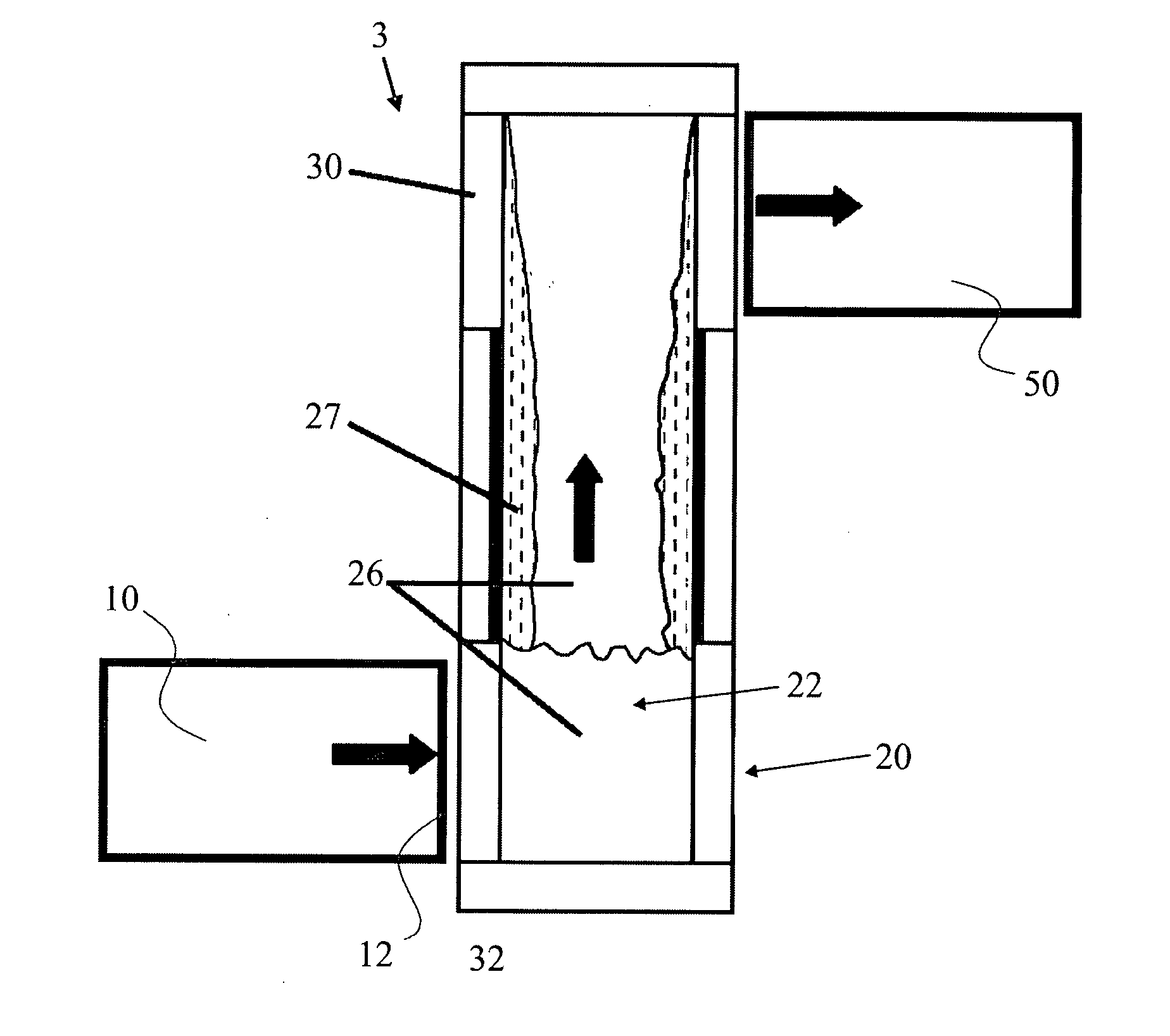
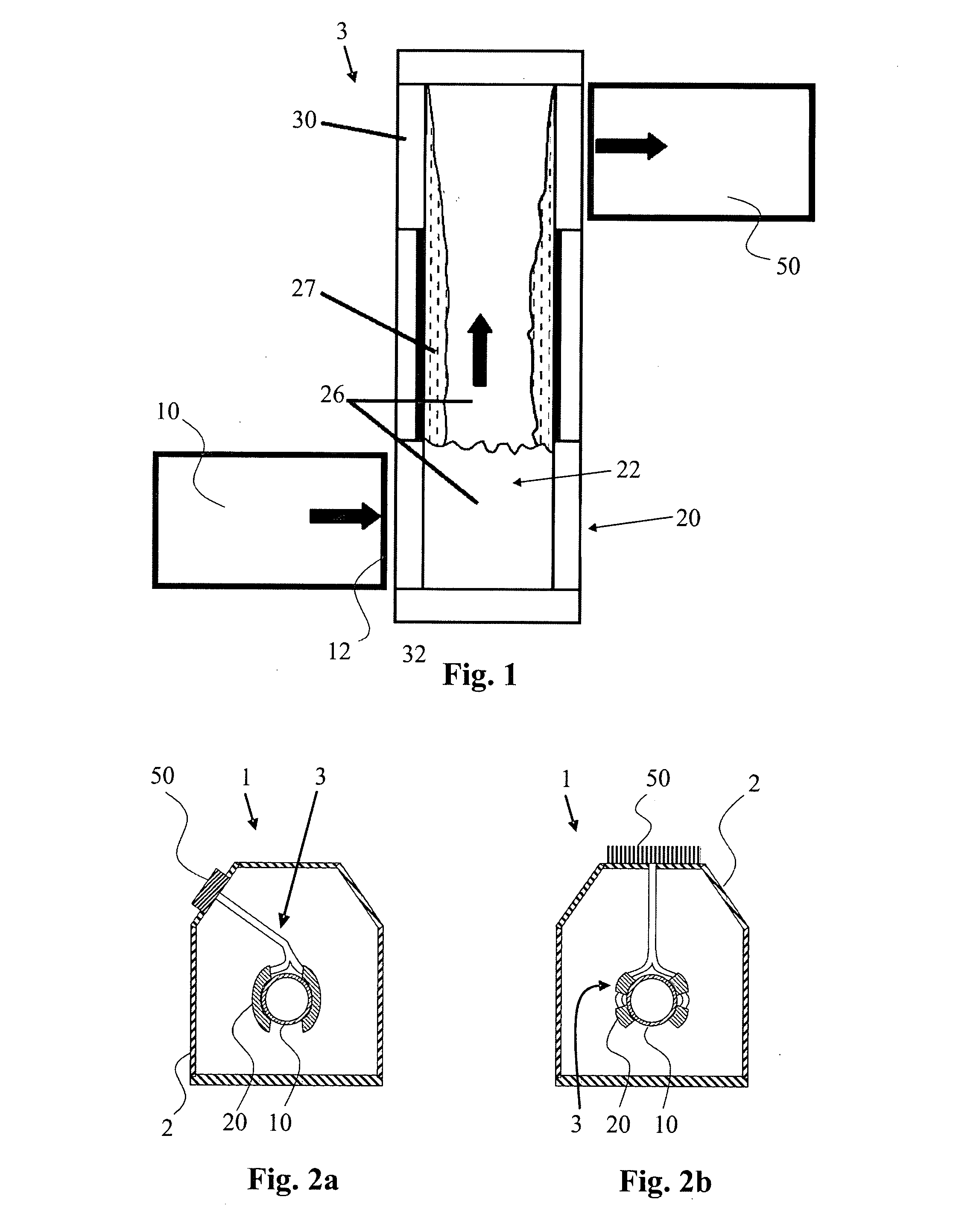
[0030]FIG. 1 shows a schematic view of a heat siphon 3 for cooling a heat source 10, for example an electrical operating means. The heat source 10 has a surface 12 to be cooled, through which heat is emitted from the heat source 10 to the heat siphon 3. The heat siphon 3 comprises a peripheral wall 30, whose internal volume 22 contains a coolant 26. The internal volume 22 is generally sealed off in a gas-tight manner from the surrounding environment. In order that the coolant 26 does not escape even during long-term operation, the sealing of the volume 22 meets the requirements for a high vacuum.

[0031]The lower region of the heat siphon 3 is in the form of an evaporator 20. The evaporator 20 is in thermal contact with the heat source 10. For this purpose, part of the peripheral wall 30 is in the form of a contact wall 32 with a contact face. The contact face is in areal contact with the surface 12 to be cooled of the heat source 10. An upper region of the heat siphon 3 is in thermal...


PUM

PropertyMeasurementUnit
pressureaaaaaaaaaa
pressureaaaaaaaaaa
contact pressureaaaaaaaaaa

Abstract

A cooling device is disclosed for an electrical operating means, which has a surface to be cooled. The cooling device comprises a coolant, a peripheral wall, whose interior defines a volume for the coolant, a fastening for fastening the cooling device to the electrical operating means, and a contact-pressure means. The peripheral wall has a thermally conductive contact wall with a contact face, which is designed for areal contact with the surface to be cooled. The contact-pressure means mechanically prestresses the contact wall in order to produce an areal contact pressure of the contact face against the surface to be cooled when the cooling device is fastened to the electrical operating means.

Description

RELATED APPLICATIONS[0001]This application claims priority under 35 U.S.C. §119 to EP Application 06405368.9 filed in Europe on Aug. 25, 2006, the entire contents of which are hereby incorporated by reference in their entireties.TECHNICAL FIELD[0002]The invention relates to a cooling device, in particular a cooling device for an electrical operating means and to an electrical operating means having a cooling device fastened thereto, as well as to a method for producing a cooling device, in particular a cooling device for an electrical operating means.BACKGROUND INFORMATION[0003]Outgoing generator lines with forced cooling are known from K. Albert et al., Elektrischer Eigenbedarf / Energietechnik in Kraftwerken und Industrie [Electrical auxiliaries service / energy technology in power stations and industry], VDE-Verlag, ISBN 3-8007-1586-4, Chapter 10.3 (pages 431-455). In order to cool the inner conductor of the outgoing generator line, an air flow is produced by means of blowers. Furthe...

Claims


Application Information

Patent Timeline
Patent Type & Authority Applications(United States)
IPC IPC(8): H02B1/56B21D53/02F28D7/00
CPCY10T29/49353H02G5/10
Inventor UNTERNAEHRER, PETERLAKNER, MARTINMAUROUX, JEAN-CLAUDECHARTOUNI, DANIELBUHLER, TILOJUST, DAVID
Owner ABB RES LTD
Why Eureka
Try Eureka