
Optical pickup device

a pickup device and optical technology, applied in the field of optical pickup devices, can solve the problems of reducing the light transmittance, affecting the quality of reproducing information and the like by the optical pickup device, and high possibility of collision between the optical recording medium and the objective lens

Inactive Publication Date: 2008-02-28
FUNAI ELECTRIC CO LTD
View PDF3 Cites 5 Cited by
  • Summary
  • Abstract
  • Description
  • Claims
  • Application Information

AI Technical Summary

Benefits of technology

[0017] In view of the above described problems, it is an object of the present invention to provide an optical pickup device which has the compatibility with three kinds of the optical recording media, in that the efficiency of optical transmission is improved, increase of number of parts which are disposed in the optical system is suppressed, and possibility of collision between the objective lens and the optical recording medium is decreased.

Problems solved by technology

Therefore, it causes a problem that possibility of collision between the optical recording medium and the objective lens becomes high.
In this case, there is a problem that a quality of reproducing information and the like by the optical pickup device becomes damaged due to generation of large coma aberration when the objective lens is shifted for tracking control and the like (hereinafter, this may be simply referred to as “lens shift”).
However, in a case where the diffraction grating is formed on the transparent member, and is disposed in the optical system of the optical pickup device, there is a problem that the light transmittance is made decrease for the light beam having the wavelength which is arranged to pass through the member inherently without being diffracted when the light beam passes through the member.
As a result, it causes a problem on efficiency of optical transmission of the optical pickup device.
However, the structure disclosed in JP-A-H10-092000 has the compatibility only with two kinds of the optical recording media, and to utilize this for the three kinds of the optical recording media, it is necessary to dispose a plurality of the liquid crystal holograms, and it causes a problem that number of parts is made increase.

Method used


Image

  • Optical pickup device
  • Optical pickup device
  • Optical pickup device

Examples


Embodiment Construction

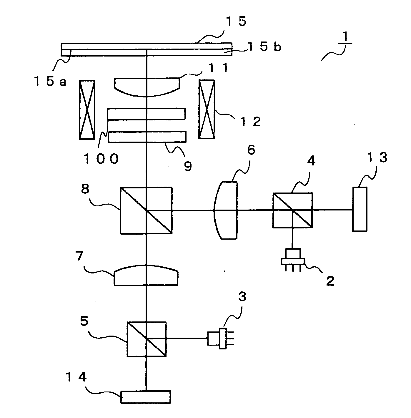
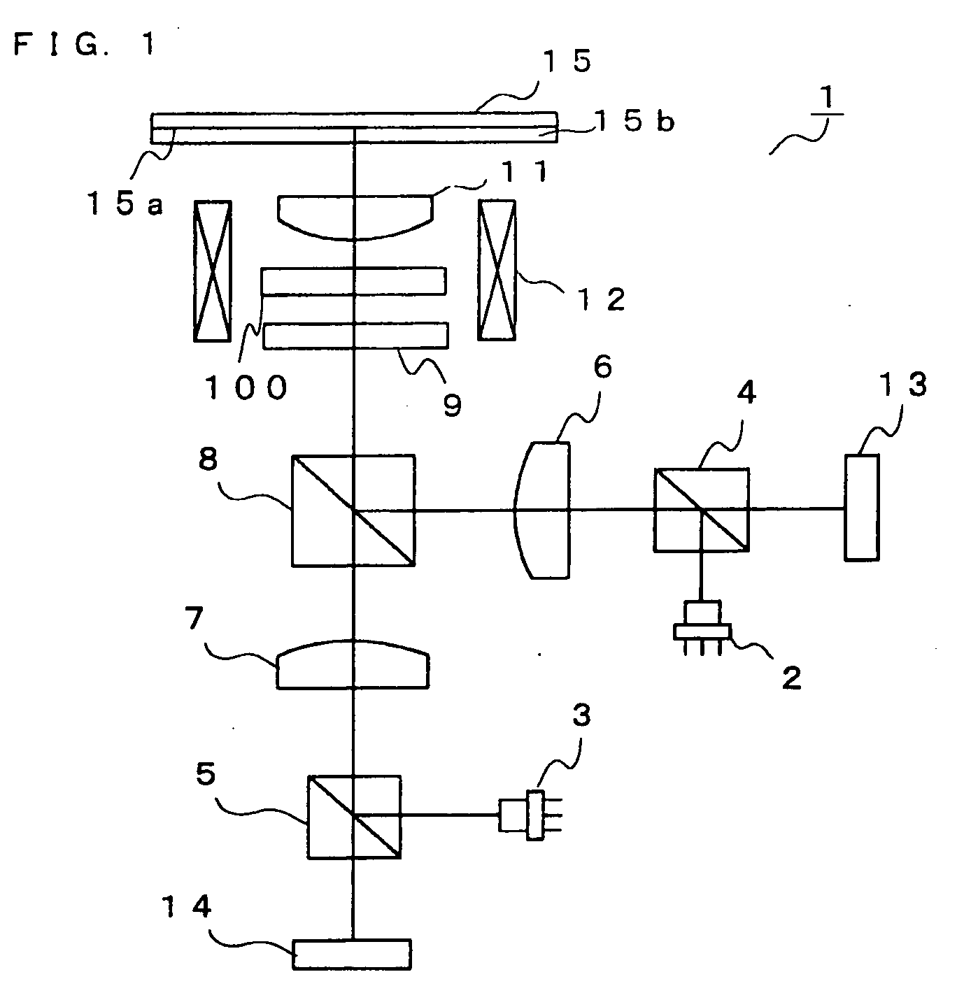
[0050] Hereinafter, contents of the present invention will be described in detail with reference to the attached drawings. However, the embodiments described here are merely examples, and the present invention is not limited to the embodiments described here. FIG. 1 is a schematic diagram to show one embodiment of an optical system of optical pickup device according to the present invention. The optical pickup device 1 according to the present embodiment is designed to be compatible with optical recording media such as a BD, a DVD, and a CD.

[0051] The optical pickup device 1 is equipped with a first light source 2 which is two wavelength combination type that can emit a light beam having the wavelength of 780 nm for a CD or a light beam having the wavelength of 650 nm for a DVD, a second light source 3 that can emit a light beam having the wavelength of 405 nm for BD, a first beam splitter 4 and a second beam splitter 5 which reflect the light beam emitted from the light sources 2,...


PUM


Abstract

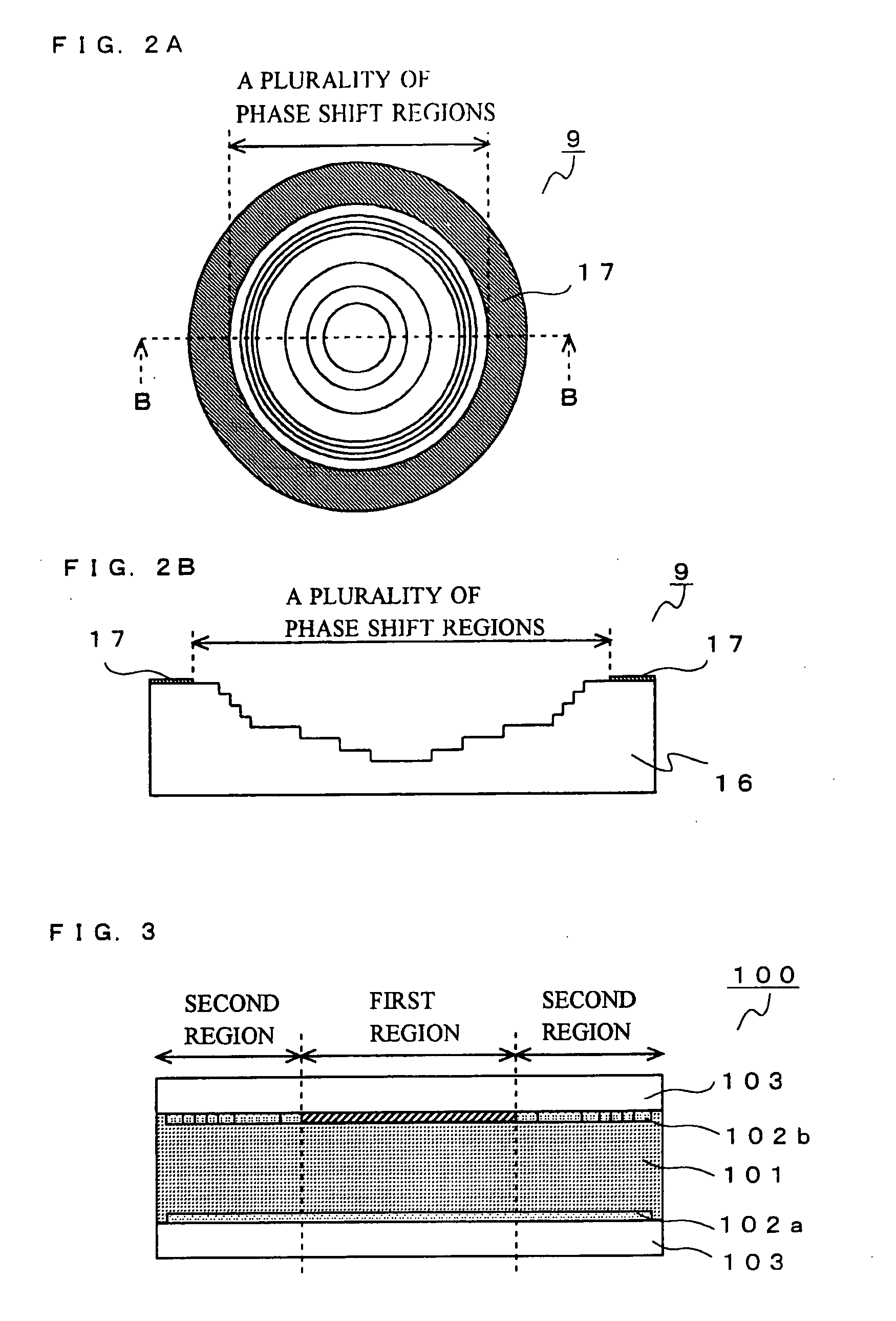
An optical pickup device includes a spherical aberration compensating element which can compensate the spherical aberration of a light beam for a BD or a CD, and a phase shift element which can compensate the spherical aberration of a light beam for a DVD. In the spherical aberration compensating element, a first region which can compensate the spherical aberration of a light beam for a CD by diffraction and diffusion, and a second region which is formed to surround the first region and can compensate the spherical aberration of a light beam for a BD by changing phase distribution, are formed. Functions of the first region and the second region can be electrically controlled in ON-OFF manner.

Description

[0001] This application is based on Japanese Patent Application No. 2006-227908 filed on Aug. 24, 2006, and the contents of which are hereby incorporated by reference. BACKGROUND OF THE INVENTION [0002] 1. Field of the Invention [0003] The present invention relates to an optical pickup device that projects a light beam to an optical recording medium so that information can be recorded and reproduced. In particular, the present invention relates to an optical pickup device which is compatible with three kinds of optical recording media utilizing light beams having different wavelengths. [0004] 2. Description of Related Art [0005] Recently, optical recording media including a compact disc (hereinafter referred to as “a CD”) and a digital versatile disc (hereinafter referred to as “a DVD”) have become commonplace and widely available. Further, in order to increase a quantity of information recorded on the optical recording medium, researches to realize higher recording density of the o...

Claims


Application Information

Patent Timeline
IPC IPC(8): G11B7/00
CPCG11B7/1353G11B7/1367G11B2007/0006G11B7/13925G11B7/1369
Inventor NISHIOKA, KENFUJII, HITOSHINAGASHIMA, KENJI
Owner FUNAI ELECTRIC CO LTD
Learn More