

Image density conversion method, image enhancement processor, and program thereof
a conversion method and image technology, applied in image enhancement, instruments, computing, etc., can solve the problems of difficult enhancement of only the target texture (fingerprint), major disincentive to automation, and difficult to enhance only the target texture, so as to prevent the enhancement of the noise area boundary, the effect of eliminating background noise and enhancing the target textur
- Summary
- Abstract
- Description
- Claims
- Application Information
AI Technical Summary
Benefits of technology
Problems solved by technology
Method used
Image

Examples
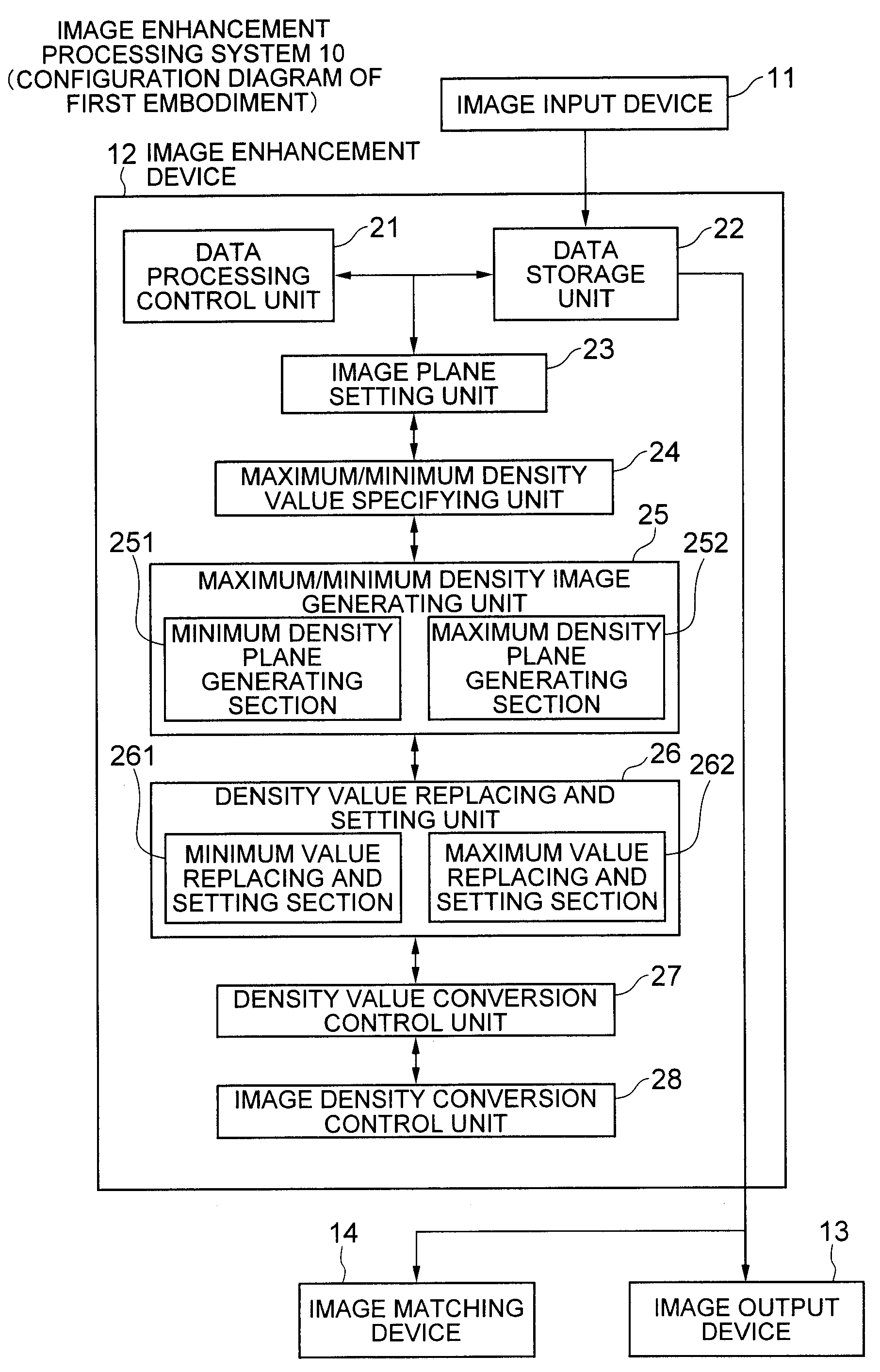
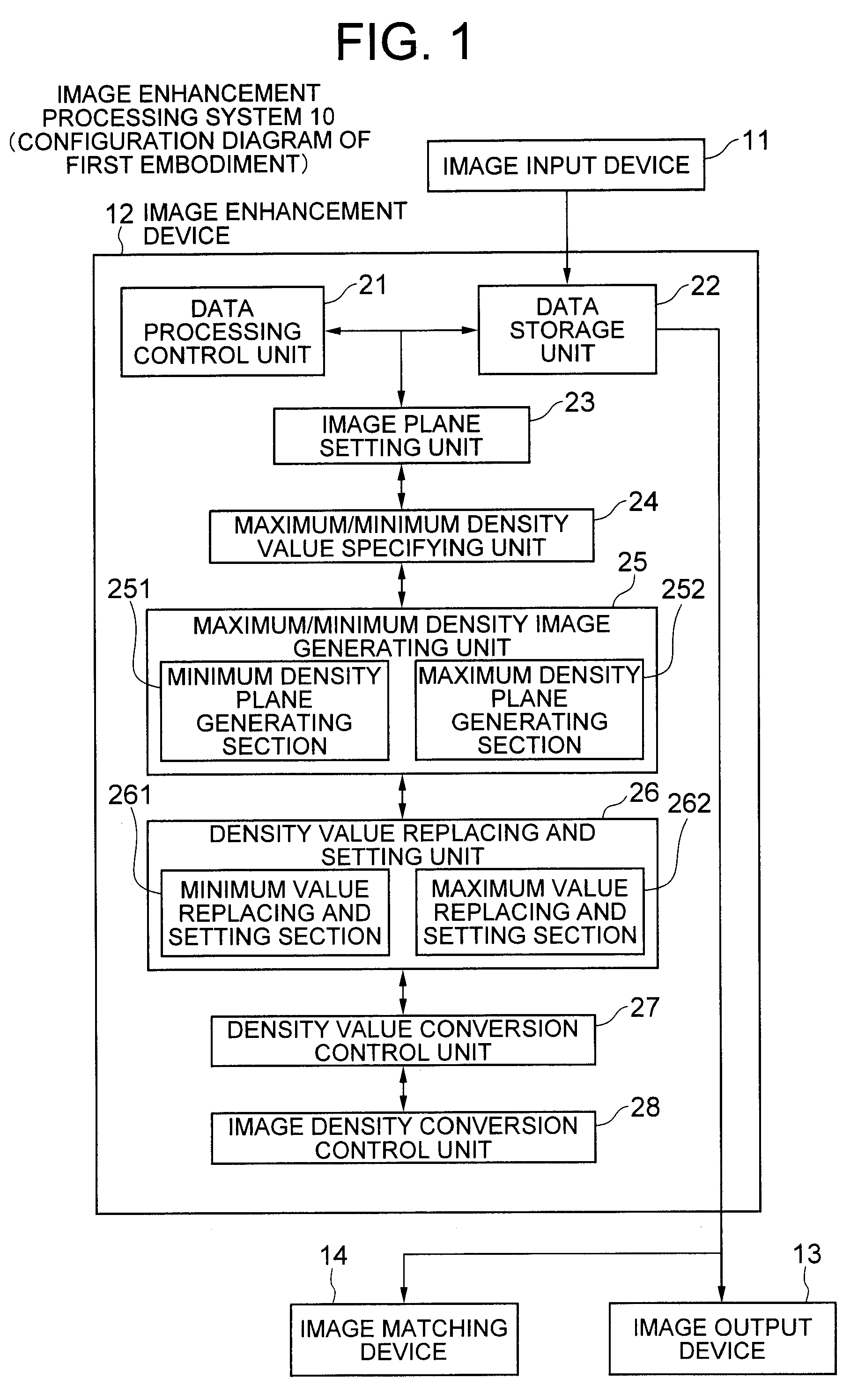
first exemplary embodiment
Operation of First Exemplary Embodiment
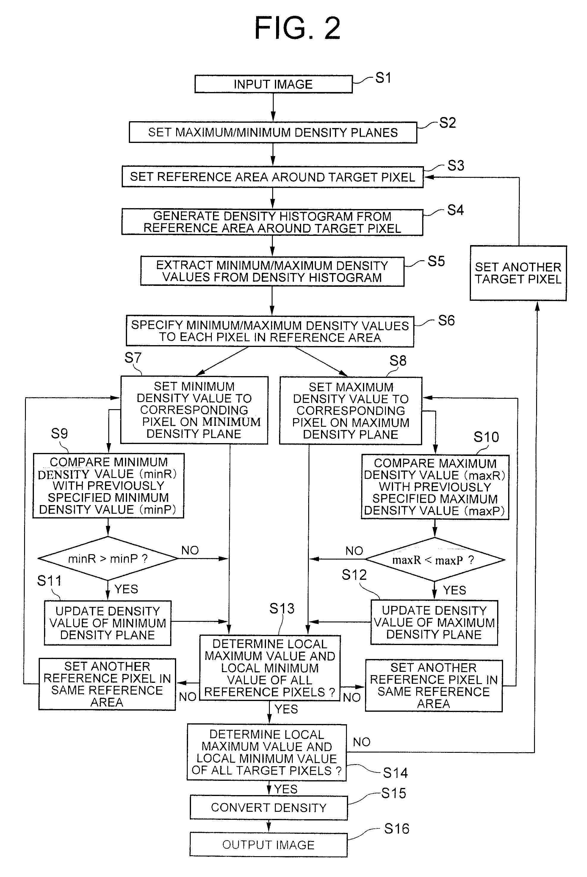
[0087]Next, overall operation of image density conversion processing in the image enhancement processing system 10 including the above-described configuration will be described.
[0088]In the first exemplary embodiment, when image information is input from the image input device 11, at least two image planes each including the same number of pixels as the pixels included in the input image are set by the image plane setting unit 23 (image plane setting step).
[0089]Next, among the pixel areas, each having a diameter of 20 pixels, set around the respective pixels of the input image while partially overlapping each other, the maximum / minimum density value specifying unit 24 first extracts a maximum density value and a minimum density value from a plurality of pixels in one pixel area, and specifies them as a common maximum density value and a common minimum density value of the pixels in the area (maximum / minimum density value specifying step).
[0090...
second exemplary embodiment
Operation of Second Exemplary Embodiment
[0142]In the second exemplary embodiment, when image is input by the image input device 31, the maximum / minimum density value extraction unit 43 sets, with respect to the pixels included in the input image, pixel areas partially overlapping each other, each of which has a diameter of 20 pixels and is set around each pixel. The maximum / minimum density value extraction unit 43 extracts, for each pixel area, the maximum density value and the minimum density value of the pixels in each pixel area, stores them in the data storage unit 42, and specifies them as the maximum density value and the minimum density value which are common to the respective pixels in each area (first step).
[0143]Then, if a plurality of maximum density values and minimum density values for the respective areas, specified in the first step, are stored in the data storage unit 42, the local density value specifying unit 44 specifies the smallest value among the stored maximum...
PUM
 Abstract
Description
Claims
Application Information