Method For Cutting Freeform Surfaces, Cutting Tool And Use Of The Cutting Tool

a freeform surface and cutting tool technology, applied in the direction of instruments, total factory control, programme control, etc., can solve the problems the relative high number of required cutting paths, and achieve the effect of reducing the time required for cutting, increasing the spacing of lines during cutting, and reducing residual lines

Active Publication Date: 2008-02-28
MTU AERO ENGINES GMBH
View PDF8 Cites 6 Cited by
  • Summary
  • Abstract
  • Description
  • Claims
  • Application Information

AI Technical Summary

Benefits of technology

[0005]According to an example embodiment of the present invention, a workpiece is cut by a cutting tool such that a desired freeform surface may be obtained. For cutting purposes, the cutting tool is moved along at least one defined cutting path relative to the workpiece. A cutting tool (a so-called special cutter) is used, the tool head of which has a greater radius than a tool shank of the cutting tool, without, however, the tool head protruding laterally beyond an outer lateral surface of the tool shank. This may provide that cutting results in low residual line formation. Accordingly, it may be possible to increase the line spacing during cutting and reduce the time required for cutting.

Problems solved by technology

This results in a relatively high number of required cutting paths, which determines the time required for cutting.

Method used


Image

  • Method For Cutting Freeform Surfaces, Cutting Tool And Use Of The Cutting Tool
  • Method For Cutting Freeform Surfaces, Cutting Tool And Use Of The Cutting Tool

Examples


Embodiment Construction

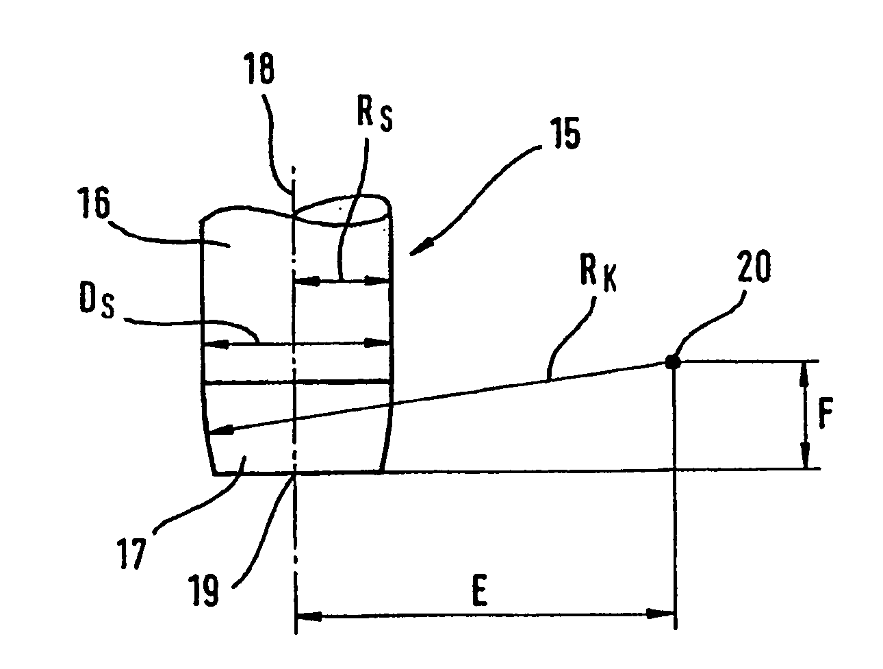
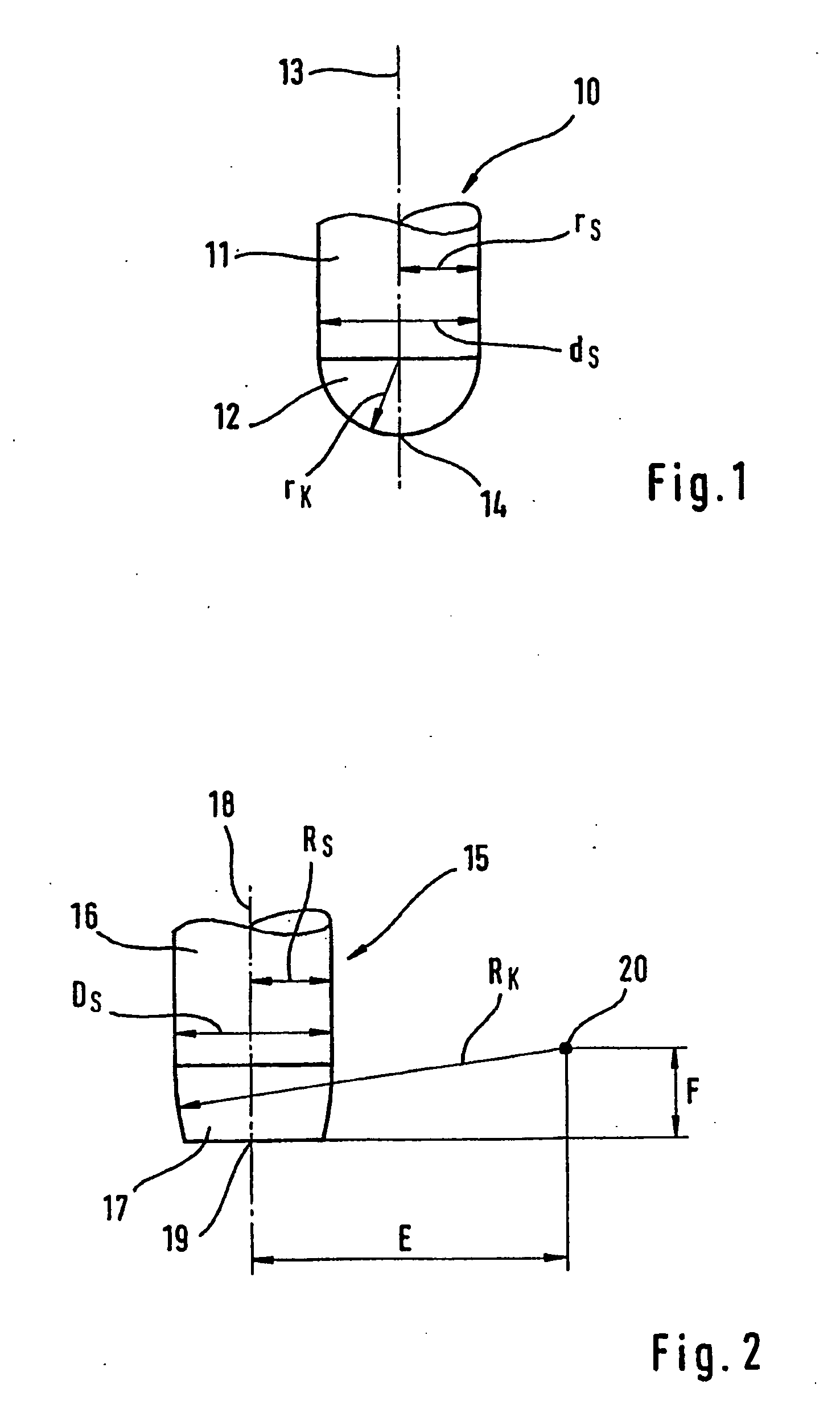
[0010]Example embodiments of the present invention are described in greater detail below with reference to the appended Figures. Before presenting the details of a method hereof and of a cutting tool hereof, however, a few aspects, to which reference will be made later, shall be mentioned below.

[0011]When cutting a workpiece to be machined, the surface of the workpiece is to obtain a desired three-dimensional geometry. This desired three-dimensional geometry on the surface of the workpiece is also referred to as a freeform surface.

[0012]The cutting of the workpiece to be machined occurs with the aid of a cutting tool, a so-called cutter. For purposes of machining the workpiece, the cutting tool or cutter is moved relative to the workpiece. The movement of the cutting tool or cutter relative to the workpiece is described by so-called tool coordinates, the tool coordinates defining the position of a tool reference point. The movement of the tool reference point in cutting the workpie...


PUM

PropertyMeasurementUnit
radiusaaaaaaaaaa
radius of curvatureaaaaaaaaaa
timeaaaaaaaaaa

Abstract

In a method for cutting freeform surfaces, a workpiece is cut by a cutting tool such that a desired freeform surface may be achieved, the cutting tool for cutting purposes being moved along at least one defined cutting path relative to the workpiece. A cutting tool is used, the tool head of which has a greater radius than a tool shank of the cutting tool.

Description

FIELD OF THE INVENTION[0001]The present invention relates to a method for cutting freeform surfaces, to a cutting tool and to the use of the cutting tool.[0002]The present invention relates to the area of cutting technology, e.g., to HSC cutting (high-speed cutting), which is also referred to as HPC cutting (high performance cutting).BACKGROUND INFORMATION[0003]Conventionally, so-called spherical cutters are used for cutting freeform surfaces. Such spherical cutters have a tool shank and a tool head attached to the tool shank, a radius of the tool head corresponding to a radius of the tool shank in the spherical cutter. The tool head therefore does not protrude laterally beyond an outer lateral surface of the tool shank.[0004]For minimizing undesired residual lines formed during cutting, the use of a spherical cutter entails restrictions with respect to the line spacing to be maintained between the cutting paths of the cutting tool. This results in a relatively high number of requir...

Claims


Application Information

Patent Timeline
Patent Type & Authority Applications(United States)
IPC IPC(8): B23C3/00B23C3/18B23C5/10G05B19/4093
CPCB23C3/18B23C5/1009B23C2215/44G05B19/40937Y10T407/1946G05B2219/35222Y10T82/10Y10T82/2502G05B2219/35185Y02P90/02
Inventor GLAESSER, ARNDTHEINRICH, STEFAN
Owner MTU AERO ENGINES GMBH
Why Eureka
Try Eureka