Turbine airfoil cooling system with perimeter cooling and rim cavity purge channels

a cooling system and airfoil technology, applied in the field of hollow cooling systems, can solve the problems of reducing the useful life affecting the cooling effect of the turbine blade, and the likelihood of failure, so as to improve the cooling effect of the airfoil tip corner, improve the production yield of the airfoil, and improve the cooling effect of the airfoil

Inactive Publication Date: 2008-02-28
SIEMENS ENERGY INC
View PDF19 Cites 12 Cited by
  • Summary
  • Abstract
  • Description
  • Claims
  • Application Information

AI Technical Summary

Benefits of technology

[0010]Another advantage of the invention is that the location of the airfoil tip cooling channel creates impingement cooling at a trailing edge corner of the tip section of the airfoil, which enhances the airfoil tip corner cooling.
[0011]Yet another advantage of this invention is that the cooling system is designed as a counterflow system in which cooling fluids travel around the perimeter of the airfoil from the trailing edge to the leading edge. Such a configuration yields a lower thermal gradient for the internal partition ribs forming the cooling channels of the cooling system.
[0012]Another advantage of this invention is that the root discharge openings provide additional support to the serpentine ceramic core during casting, which translates into improved production yields of the airfoil.
[0013]These and other embodiments are described in more detail below.

Problems solved by technology

In addition, turbine blades often contain cooling systems for prolonging the life of the blades and reducing the likelihood of failure as a result of excessive temperatures.
However, centrifugal forces and air flow at boundary layers often prevent some areas of the turbine blade from being adequately cooled, which results in the formation of localized hot spots.
Localized hot spots, depending on their location, can reduce the useful life of a turbine blade and can damage a turbine blade to an extent necessitating replacement of the blade.

Method used


Image

  • Turbine airfoil cooling system with perimeter cooling and rim cavity purge channels
  • Turbine airfoil cooling system with perimeter cooling and rim cavity purge channels
  • Turbine airfoil cooling system with perimeter cooling and rim cavity purge channels

Examples


Embodiment Construction

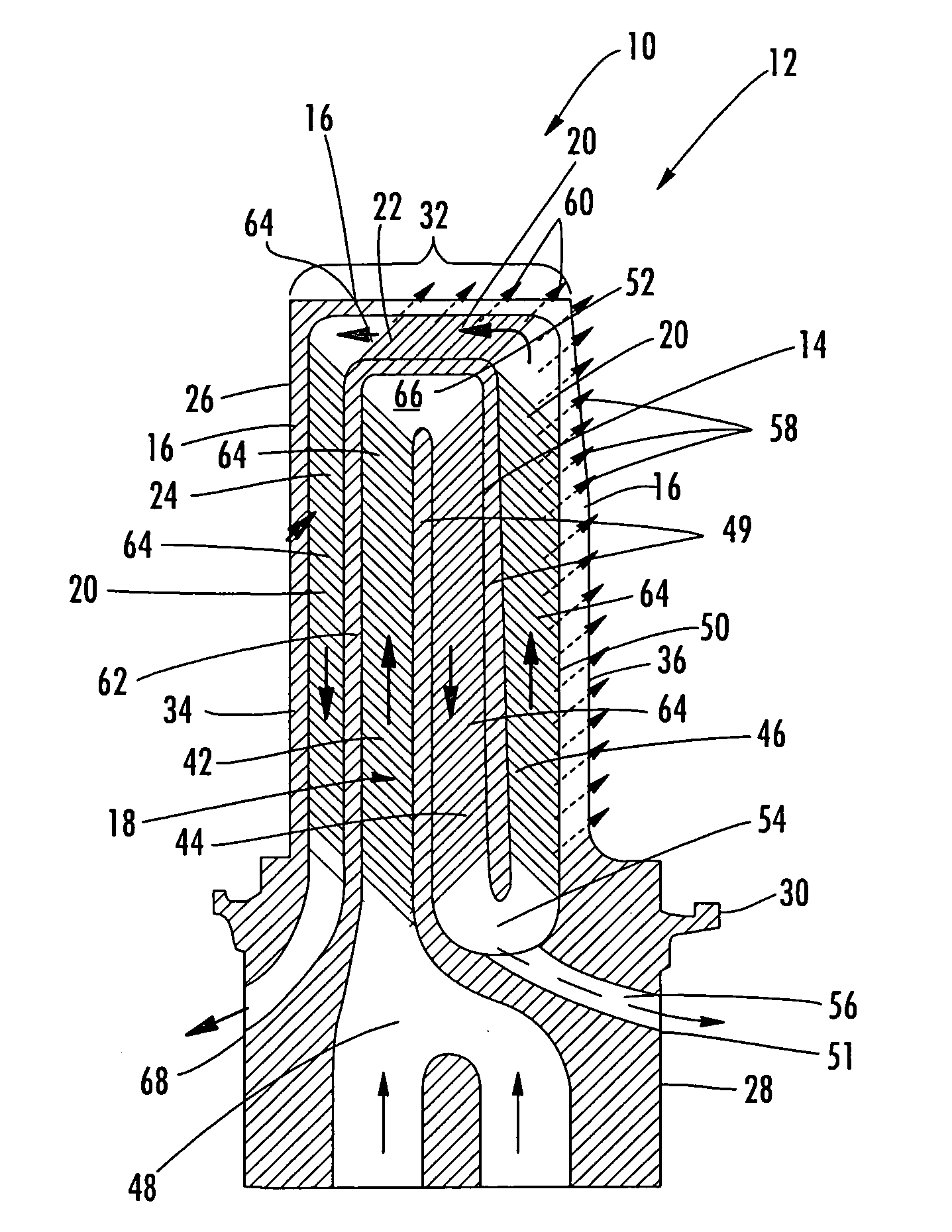
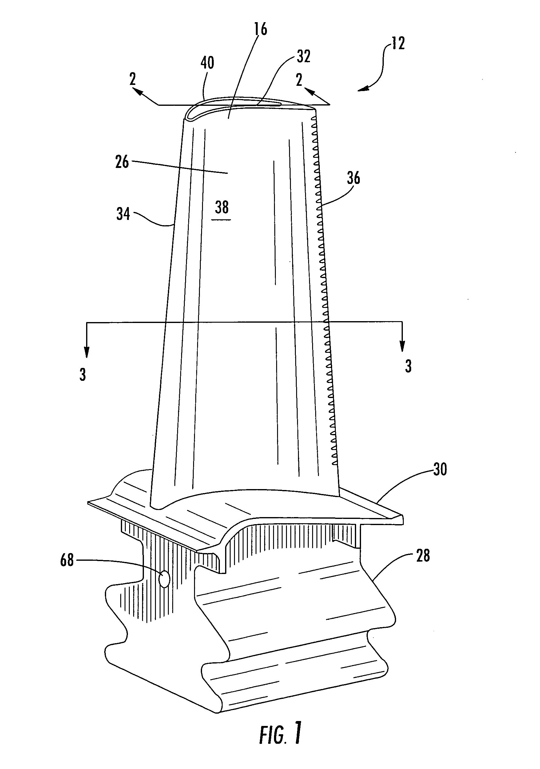
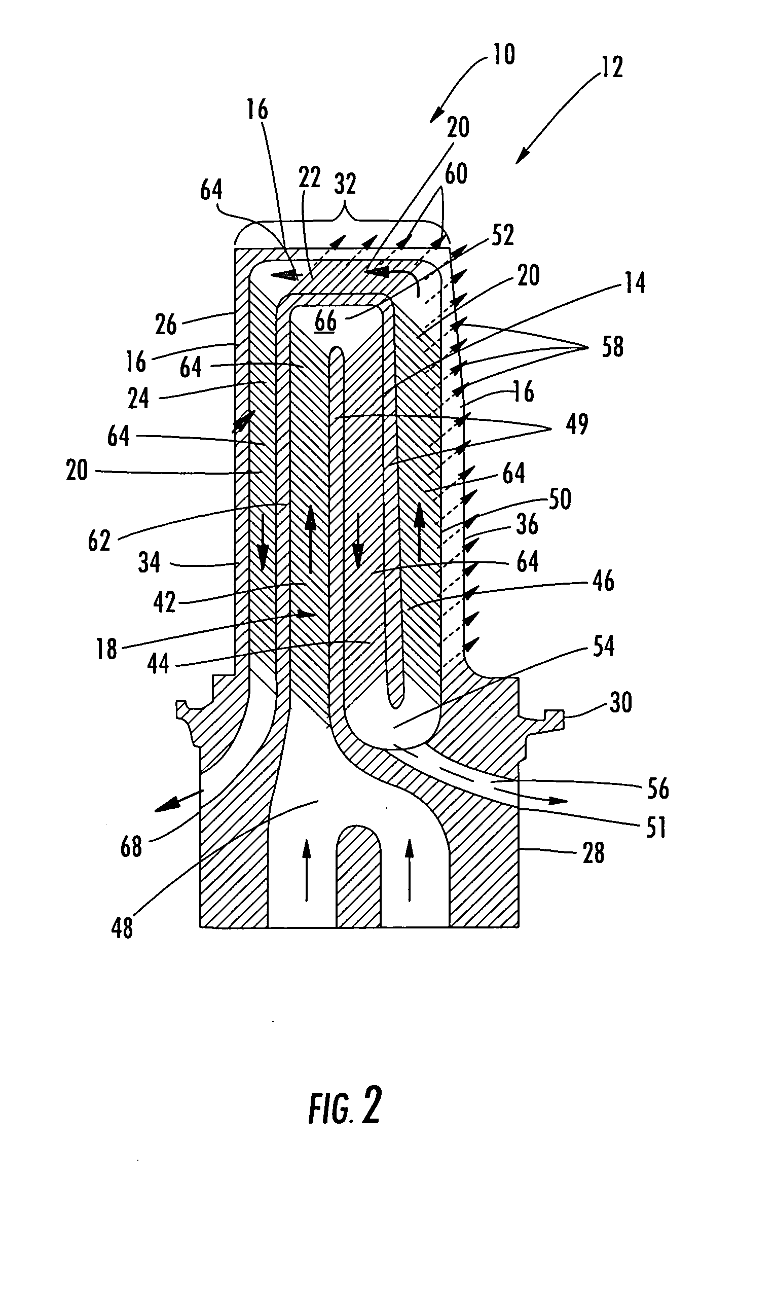
[0020]As shown in FIGS. 1-5, this invention is directed to a turbine airfoil cooling system 10 for a turbine airfoil 12 used in turbine engines. In particular, the turbine airfoil cooling system 10 includes a plurality of internal cavities 14, as shown in FIG. 3, positioned between outer walls 16 of the turbine airfoil 12. The cavity 14 may be formed from a mid-chord serpentine cooling channel 18 in fluid communication with a perimeter cooling system 20. The perimeter cooling system 20 may be formed from an airfoil tip cooling channel 22 and a third leg 24. The perimeter cooling system 20 may exhaust at least a portion of the cooling fluids from the airfoil 12 through cooling channels in a root 28 of the airfoil 12.

[0021]The turbine airfoil 12 may be formed from a generally elongated, hollow airfoil 26 coupled to the root 28 at a platform 30. The turbine airfoil 12 may be formed from conventional metals or other acceptable materials. The generally elongated airfoil 26 may extend fro...


PUM


Abstract

A cooling system for a turbine airfoil of a turbine engine having a perimeter cooling channel formed from a portion of a serpentine cooling channel, an airfoil tip cooling channel, and a leading edge cooling channel. The cooling system also includes cooling channels enabling cooling fluids to be discharged into the root of the airfoil to cool rim cavities and purge air therein. The cooling system may be configured such that the cooling fluids may pass into a mid-chord serpentine cooling channel, flow through the serpentine cooling channel generally in a chordwise direction from the leading edge toward the trailing edge, flow toward the tip section and along the trailing edge, flow from the trailing edge toward the leading edge in the airfoil tip cooling channel, flow along the leading edge in the leading edge cooling channel, through the root of the blade, and be exhausted into a rim cavity.

Description

FIELD OF THE INVENTION[0001]This invention is directed generally to turbine airfoils, and more particularly to cooling systems in hollow turbine airfoils.BACKGROUND[0002]Typically, gas turbine engines include a compressor for compressing air, a combustor for mixing the compressed air with fuel and igniting the mixture, and a turbine blade assembly for producing power. Combustors often operate at high temperatures that may exceed 2,500 degrees Fahrenheit. Typical turbine combustor configurations expose turbine blade assemblies to these high temperatures. As a result, turbine blades must be made of materials capable of withstanding such high temperatures. In addition, turbine blades often contain cooling systems for prolonging the life of the blades and reducing the likelihood of failure as a result of excessive temperatures.[0003]Typically, turbine blades are formed from a root portion having a platform at one end and an elongated portion forming a blade that extends outwardly from t...

Claims


Application Information

Patent Timeline
Patent Type & Authority Applications(United States)
IPC IPC(8): F01D5/18
CPCF01D5/187F05D2240/304F05D2240/122
Inventor LIANG, GEORGE
Owner SIEMENS ENERGY INC
Why Eureka
Try Eureka