Rare Earth Magnet and Method for Manufacturing Same

a technology manufacturing methods, applied in the field of rare earth magnets, can solve the problems of relatively low corrosion resistance of these magnets, and achieve the effect of sufficient corrosion resistan

Inactive Publication Date: 2008-02-28
TDK CORPARATION
View PDF5 Cites 35 Cited by
  • Summary
  • Abstract
  • Description
  • Claims
  • Application Information

AI Technical Summary

Benefits of technology

[0063]The present invention can provide a rare-earth magnet having a s

Problems solved by technology

Though the rare-earth magnets exhibit a high energy product, their corrosion resistance is relatively low

Method used


Image

  • Rare Earth Magnet and Method for Manufacturing Same
  • Rare Earth Magnet and Method for Manufacturing Same
  • Rare Earth Magnet and Method for Manufacturing Same

Examples


first embodiment

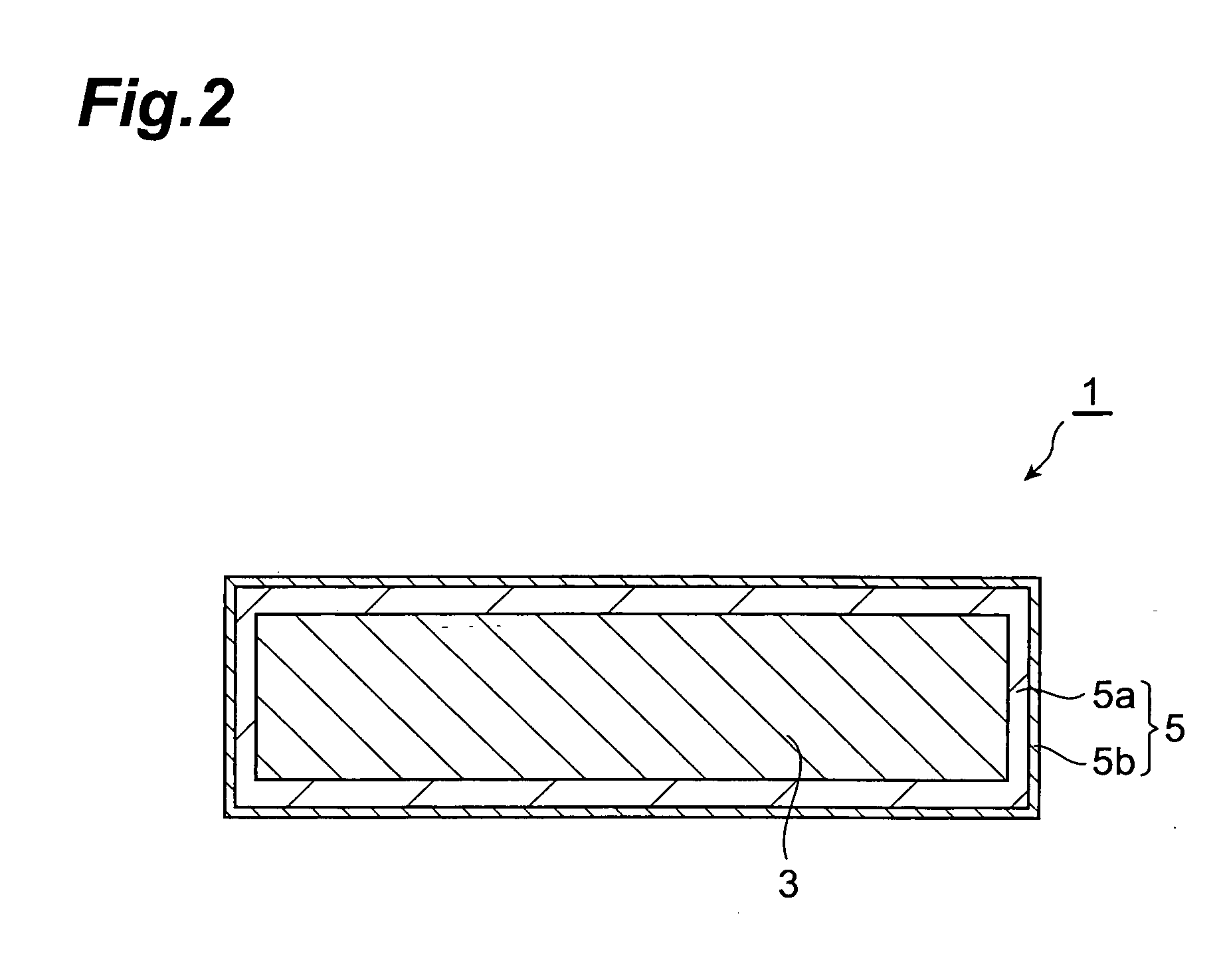
[0084]To begin with, a first embodiment of the rare-earth magnet and method of manufacturing the same in accordance with the present invention will be explained. The rare-earth magnet of the first embodiment comprises a magnet body containing a rare-earth element, and a protective layer formed on a surface of the magnet body, whereas the protective layer includes a first layer covering the magnet body and containing a rare-earth element, and a second layer covering the first layer and containing substantially no rare-earth element.

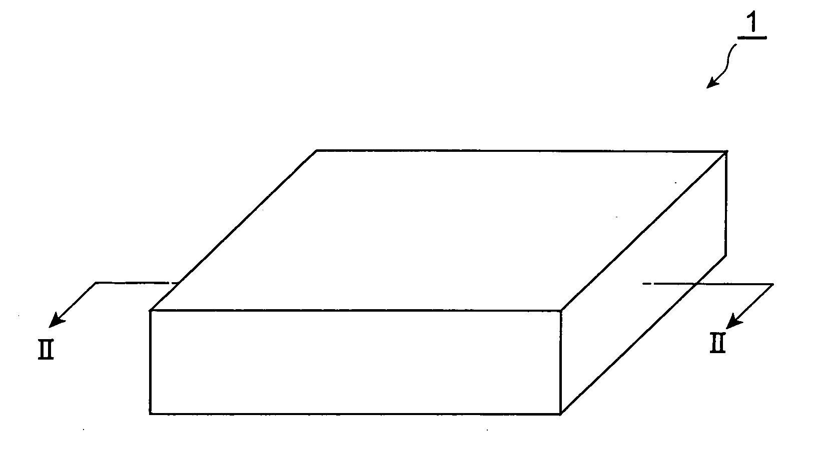
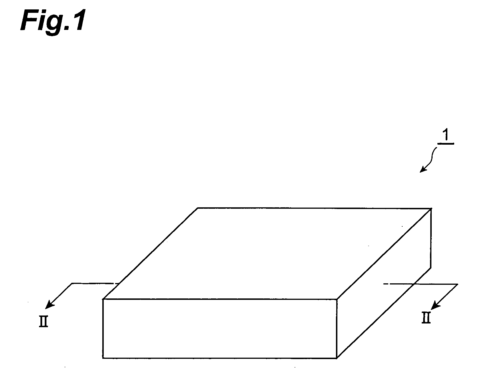
[0085]FIG. 1 is a schematic perspective view showing the rare-earth magnet in accordance with the first embodiment. FIG. 2 is a view schematically showing a cross-sectional structure appearing when the rare-earth magnet shown in FIG. 1 is cut along the line II-II. As shown in FIGS. 1 and 2, the rare-earth magnet 1 of this embodiment is constructed by a magnet body 3 and a protective layer 5 formed so as to cover all the surfaces of the magnet body 3.

[0086]...

second embodiment

[0120]A second embodiment of the rare-earth magnet and method of manufacturing the same in accordance with the present invention will now be explained. The rare-earth magnet of the second embodiment comprises a magnet body containing a rare-earth element, and a protective layer formed on a surface of the magnet body, whereas the protective layer includes an inner protective layer containing a rare-earth element and / or a transition element and oxygen, and an outer protective layer made of a constituent material different from that of the inner protective layer. In the rare-earth magnet of the second embodiment, the inner protective layer has a structure comprising a first layer covering the magnet body and containing a rare-earth element, and a second layer covering the first layer and containing substantially no rare-earth element.

[0121]FIG. 3 is a schematic perspective view showing the rare-earth magnet in accordance with the second embodiment. FIG. 4 is a view schematically showin...

examples

[0213]In the following, the present invention will be explained in further detail with reference to Examples, which do not restrict the present invention.


PUM

PropertyMeasurementUnit
Timeaaaaaaaaaa
Timeaaaaaaaaaa
Thicknessaaaaaaaaaa

Abstract

The object of the present invention is to provide a rare-earth magnet having a sufficient corrosion resistance, and a method of manufacturing the same. The rare-earth element in accordance with a preferred embodiment comprises a magnet body containing a rare-earth element, and a protective layer formed on a surface of the magnet body. The protective layer in accordance with a preferred embodiment includes a first layer covering the magnet body and containing a rare-earth element, and a second layer covering the first layer and containing substantially no rare-earth element. Another protective layer in accordance with a preferred embodiment comprises an inner protective layer and an outer protective layer successively from the magnet body side. The outer protective layer is any of an oxide layer, a resin layer, a metal salt layer, and a layer containing an organic-inorganic hybrid compound.

Description

TECHNICAL FIELD[0001]The present invention relates to a rare-earth magnet, a rare-earth magnet having a surface formed with a protective layer in particular, and a method of manufacturing the same.BACKGROUND ART[0002]As permanent magnets exhibiting a high energy product of 25 MGOe or greater, so-called rare-earth magnets (R—Fe—B magnets, where R is a rare-earth element such as neodymium as in the following) have been developed. As such rare-earth magnets, for example, Patent Documents 1 and 2 disclose one formed by sintering and one formed by rapid cooling, respectively.[0003]Though the rare-earth magnets exhibit a high energy product, their corrosion resistance is relatively low since they contain a rare-earth element and iron which are relatively easy to oxidize as main ingredients.[0004]For ameliorating the corrosion resistance of such rare-earth magnets, it has been proposed to form a protective layer. Among them, Patent Document 3 proposes to form a protective layer by heating ...

Claims


Application Information

Patent Timeline
IPC IPC(8): B32B15/04C23C16/40B22F3/24C09D5/08C22C33/02C23C22/18C23C22/42C23C22/73C23C22/74H01F1/055H01F1/057H01F7/02H01F41/02
CPCC09D5/08Y10T428/26C23C22/18C23C22/42C23C22/73C23C22/74H01F1/0577H01F41/026C22C33/0278B22F2999/00B22F2998/10B22F2009/044B22F2009/043B22F2009/041B22F2003/248B22F9/04B22F3/02B22F3/10B22F3/24B22F2202/05B22F2201/10B22F2201/20Y10T428/31678H01F1/0572
Inventor MIWA, MASASHISAKAMOTO, TAKESHIHAGIWARA, JUNMORI, MASAMINAKANO, MUTSUKOKAWAHARA, HIROSHIKITAMURA, HIROKI
Owner TDK CORPARATION
Why Eureka
Try Eureka