Window Wiping Device, Particularly For A Motor Vehicle

a technology for windshield wipers and motor vehicles, which is applied in vehicle maintenance, vehicle cleaning, roofs, etc., can solve the problems of high installation costs, high installation costs, and high installation costs, and achieves the effect of reducing the number of vehicles

Inactive Publication Date: 2008-03-06
ROBERT BOSCH GMBH
View PDF0 Cites 10 Cited by
  • Summary
  • Abstract
  • Description
  • Claims
  • Application Information

AI Technical Summary

Benefits of technology

[0005]It is particularly advantageous if the driving element has a driven shaft and the fastening elements are positioned such that the driving element can be fastened by being rotated around an axis that runs essentially parallel to the driven shaft. In this way, several fastening elements can be brought into engagement with the receptacles in the motor vehicle in one work step. This saves time in manufacturing and reduces the complexity of the manufacturing step.
[0007]It is particularly advantageous in this connection if the fastening elements are each arranged essentially on a common circle. In this way, it is especially simple to place the driving element on the body and fasten it in the motor vehicle by a simple rotational movement.
[0008]A receptacle for a rivet or a screw or a clip is provided as a locking element for fixing the driving element. It is especially advantageous if the locking element itself is embodied as a clip.
[0009]In one variation, it is advantageous to embody the locking element as a weld or an adhesive joint. As a result, an optimal hold of the driving device in the vehicle is achieved by means of an integral connection, for example.
[0010]A windshield wiper device in accordance with the pre-characterizing clause of claim 1 advantageously features a driving element, which has a fastening element at its disposal, on which an adhesive for adhering to the vehicle is applied, covered by protection. In this case, it is particularly advantageous if a damping element is arranged between the driving device and the adhesive.
[0011]In one variation, small quantities or drops of adhesive are advantageously enclosed by protection, which automatically destroys itself during connection to the vehicle permitting the adhesive to exit.
[0012]A simple variation is advantageously produced in that the protection is embodied as a protective film, which can be detached before connection with the vehicle or can be destroyed during connection. It is especially advantageous if, in terms of these kinds of connections, the adhesive is embodied as a multi-component adhesive.
[0017]As a rule, it is sufficient for the assembly opening to be punched in a flat wall of the vehicle body. In order to obtain a more dimensionally stable connection of the windshield wiper device to the vehicle body and create a free space for the driving element, it is expedient to provide the assembly opening in a deep-drawn cavity of the body. Moreover, the assembly opening can also be arranged in a correspondingly designed sheet metal part which is welded to the vehicle body.
[0017]As a rule, it is sufficient for the assembly opening to be punched in a flat wall of the vehicle body. In order to obtain a more dimensionally stable connection of the windshield wiper device to the vehicle body and create a free space for the driving element, it is expedient to provide the assembly opening in a deep-drawn cavity of the body. Moreover, the assembly opening can also be arranged in a correspondingly designed sheet metal part which is welded to the vehicle body.
[0015]According to an embodiment of the invention, the fastening element is slid in a first assembly direction running in the longitudinal direction of the driven shaft into an assembly opening of the body. Said fastening element can be locked in the assembly opening in a second assembly direction running in the circumferential direction of the rotation around which the driving element is rotated during assembly so that it can no longer be pulled out of assembly opening. For this purpose, the fastening element expediently has a U-shaped cross-sectional profile, which is open in the second assembly direction, and into which a damping element is inserted. Said damping element has a slot that is also open towards the open side into which the edge of the assembly opening can be slid. As a result, all of these types of fastening locations, which lie on one or more concentric circles around the rotational axis, can be mounted with a rotational movement of the driving element. Said rotational axis advantageously lies coaxially or axially parallel to the driven axis. The locking element prevents the fastening locations from being detached unintentionally. Furthermore, it is possible to arrange the fastening elements in such a way that the gravitational force of the driving element presses the fastening elements against the edge of the assembly opening.
[0016]For easier assembly of the windshield wiper device it is advantageous if the fastening element has a guide surface, with which it can glide during assembly in the first assembly direction along an edge of the assembly opening and be guided thereby. In this case, in accordance with another embodiment of the invention, the fastening element has a limit stop, which restricts the assembly movement in the first assembly direction.
[0017]As a rule, it is sufficient for the assembly opening to be punched in a flat wall of the vehicle body. In order to obtain a more dimensionally stable connection of the windshield wiper device to the vehicle body and create a free space for the driving element, it is expedient to provide the assembly opening in a deep-drawn cavity of the body. Moreover, the assembly opening can also be arranged in a correspondingly designed sheet metal part which is welded to the vehicle body.

Problems solved by technology

Typically, these types of driving elements are screwed down to the vehicle body, which, however, is very expensive and necessitates a lot of parts such as screws, screw nuts and washers, etc.
This is expensive logistically as well as complex in terms of installation.
Since the assembly directions of the first and second fastening elements run at one angle, it cannot be ruled out that the supporting structure will be subjected to stress after assembly, which is transmitted to adjacent parts of the body.

Method used


Image

  • Window Wiping Device, Particularly For A Motor Vehicle
  • Window Wiping Device, Particularly For A Motor Vehicle
  • Window Wiping Device, Particularly For A Motor Vehicle

Examples


Embodiment Construction

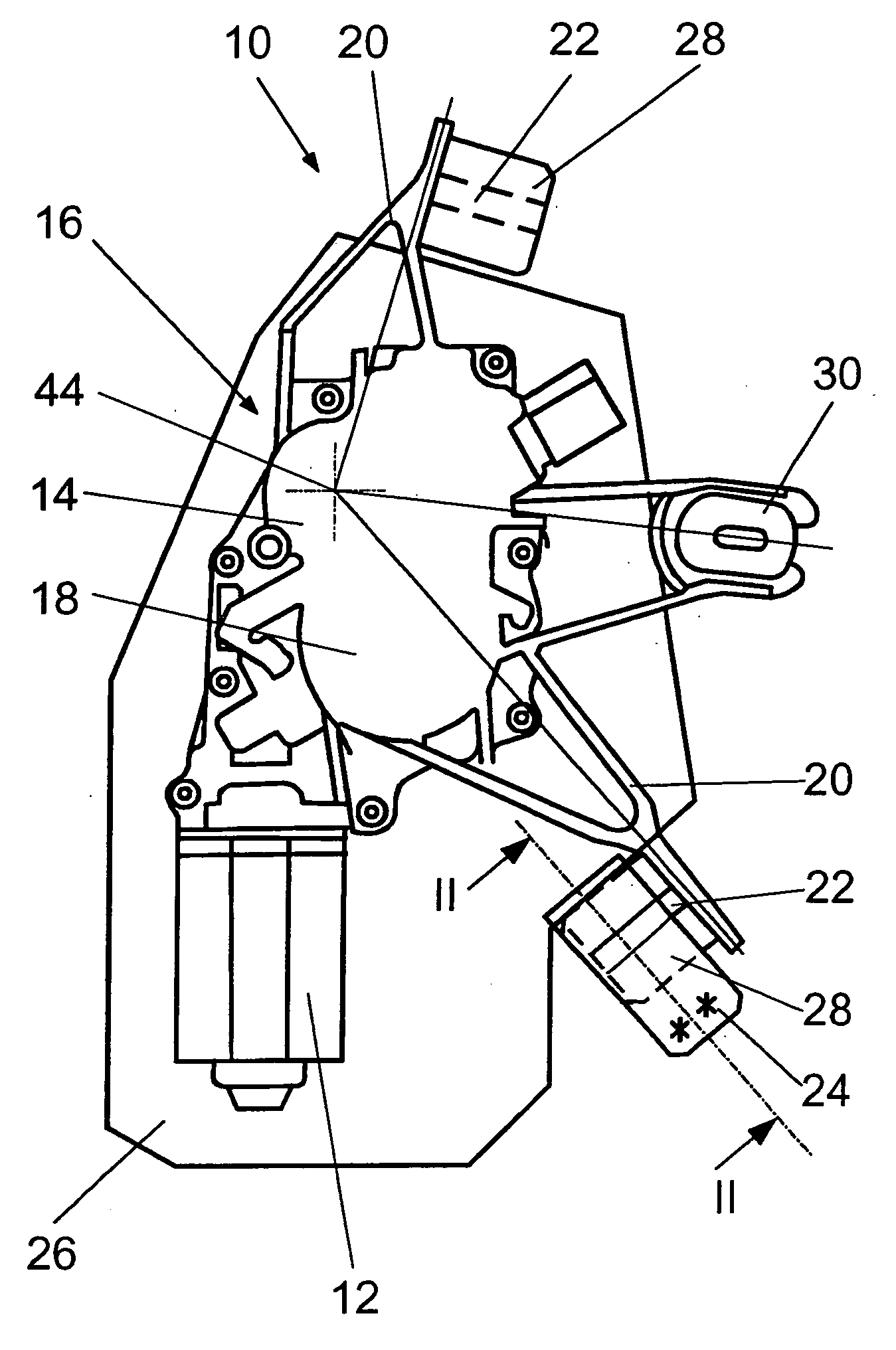
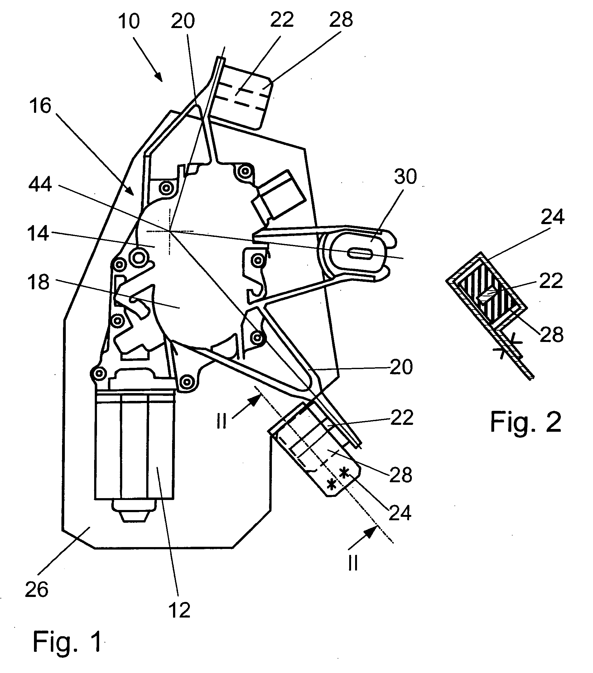
[0026]FIG. 1 shows a schematic depiction of a windshield wiper device 10 of a rear windshield of a motor vehicle. Naturally, the invention is in no way restricted to rear windshield wipers and is applicable without a problem to front windshield wipers. The windshield wiper device 10 is comprised of an electric motor 12 with a gear mechanism 14, which together form a driving element 16. The driving element 16 has a housing 18, which is made partially of cast material and from which fastening arms 20 extend radially, on each of whose ends a fastening element 22 is arranged. The fastening elements 22 are embodied here as rectangular parallelepiped-shaped rods, which extend perpendicular to the radial direction of the longitudinal extension of the fastening arms 20. Naturally, the fastening elements 22 can also be embodied otherwise. Thus, cylindrical or elliptical fastening elements 22 are also conceivable for example. In addition, the fastening elements 22 are arranged in such a way t...


PUM


Abstract

The invention starts with a windshield wiper device (10), in particular for a motor vehicle, comprising at least one driving element (16) that can be fastened to the motor vehicle, at least two essentially elongate fastening elements (22, 48) which are disposed in an axially rigid manner and are able to engage in receptacles (24, 46) of the motor vehicle, and at least one damping element (28, 60) for damping mechanical vibrations. It is proposed that the driving element (16) has a driven shaft (44) and the fastening elements (22, 48) are positioned such that the driving element (16) can be fastened by being rotated around the driven shaft (44) or an axis that runs essentially parallel thereto.

Description

Prior Art[0001]The invention relates to a windshield wiper device, in particular for a motor vehicle, in accordance with the species of the independent claims.[0002]Numerous windshield wiper devices for motor vehicles that have a driving element that is fastened to the body of the motor vehicle are already known. Typically, these types of driving elements are screwed down to the vehicle body, which, however, is very expensive and necessitates a lot of parts such as screws, screw nuts and washers, etc. This is expensive logistically as well as complex in terms of installation. In addition, a windshield wiper device is known from DE 100 62 617 A 1, which is glued into the motor vehicle, whereby the adhesive possesses damping properties.[0003]A windshield wiper system for vehicles is known for DE 198 33 404 A1, which makes assembly without screws possible and is therefore quick and simple to perform. To do this, the windshield wiper system features a supporting structure for a driving ...

Claims


Application Information

Patent Timeline
Patent Type & Authority Applications(United States)
IPC IPC(8): B60S1/04
CPCB60S1/0438B60S1/0447B60S1/0444B60S1/0441B60S1/04
Inventor ALBRECHT, GERARDBOHN, ROLANDSCHABANEL, FRANCOISRITT, JEAN-MARC
Owner ROBERT BOSCH GMBH
Why Eureka
Try Eureka