Fuel tank

a technology of fuel tanks and tanks, applied in the field of fuel tanks, can solve the problem that the waste liquid cannot be completely discharged, and achieve the effect of increasing the size of the tank

Inactive Publication Date: 2008-03-06
HITACHI LTD
View PDF5 Cites 13 Cited by
  • Summary
  • Abstract
  • Description
  • Claims
  • Application Information

AI Technical Summary

Benefits of technology

[0006]In a case where a fuel chamber and a waste liquid chamber are elastic bags in the tank of JP-A-2004-250059, there is a provability of that the fuel or waste liquid leaks out from the bag resiliently deformable. Further, in the tank of JP-A-2004-250059, a pump is arranged on a part of a pipe for collecting the waste liquid so that a pump is used to take the fuel from a fuel supply device into the tank and another pump is used to take the waste liquid out of the tank. Further, an electric power supply for the pumps are necessarily used to increase a size of the tank.

Problems solved by technology

Further, in the tank of JP-A-2004-250059, the waste liquid cannot be wholly discharged when the fuel does not fill the tank.

Method used


Image

  • Fuel tank
  • Fuel tank
  • Fuel tank

Examples


first embodiment

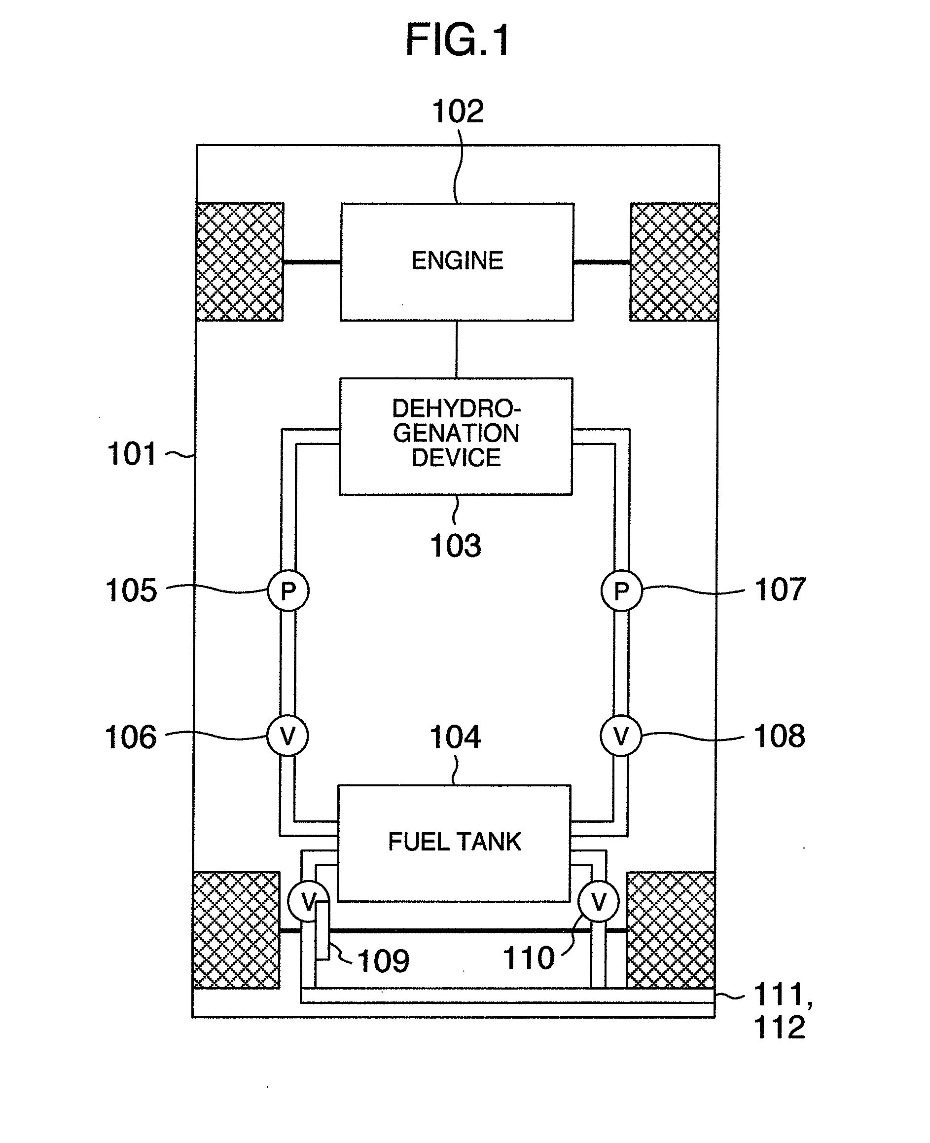
[0038]FIG. 1 is a schematic view of a hydrogen automobile with a fuel tank for automobile as an embodiment of the invention. The hydrogen automobile 101 is activated as follows. A fuel (hydrogen storage material) is fed by a pump 105 from a fuel tank 104 to a dehydrogenation device 103 and subsequently sprayed onto a catalyst layer in the dehydrogenation device 103 to be decomposed into hydrogen and a dehydrogenation product (waste liquid) with a catalysis so that the hydrogen is supplied into an engine 102 to be burnt to generate an output power. The waste liquid is withdrawn into the fuel pump 104 by a pump 107.

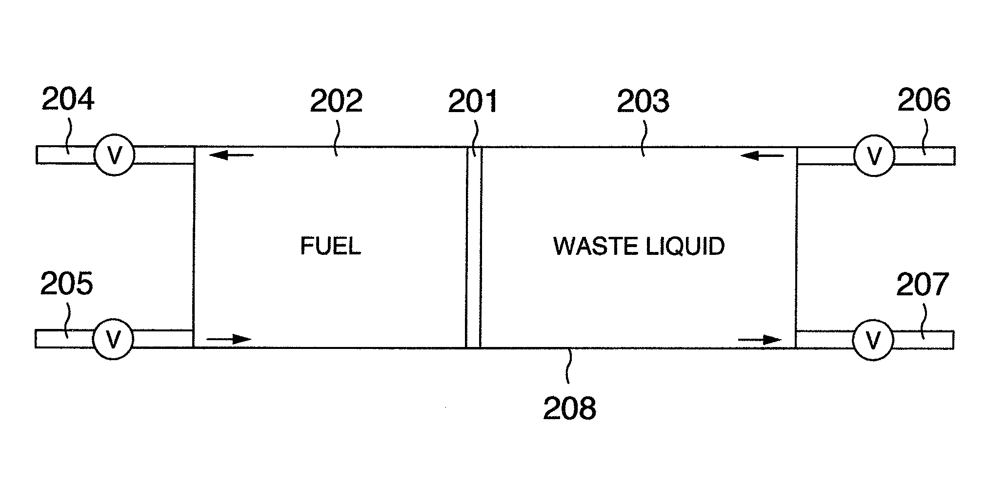
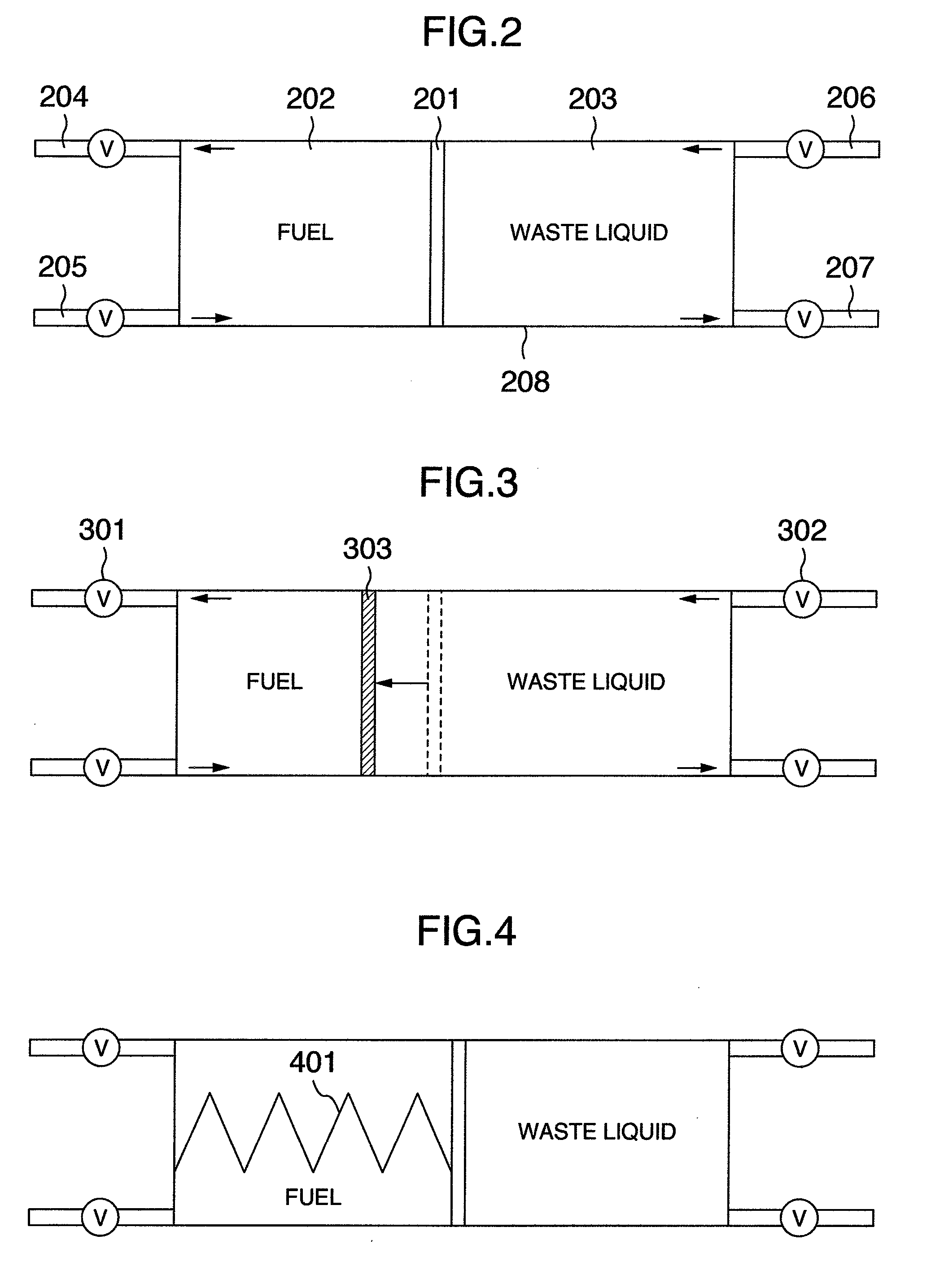
[0039]FIG. 2 is a schematic view of an embodiment of the fuel tank of the invention. The fuel tank of the embodiment includes a tank frame 208 as an outer envelope of the fuel tank, a fuel chamber 202 for containing the fuel, a waste liquid chamber 203 for containing the waste liquid, a partition wall 201 connected to the tank frame, separating fluidly the fuel chamber and ...

second embodiment

[0051]FIG. 12 is a schematic view showing a fuel tank of embodiment of the invention at the service station. The fuel tank at the service station is attached to the dispenser. Although only the fuel is taken out through the conventional dispenser for gasoline or diesel oil from the fuel tank at the dispenser side to be fed into the tank of automobile, the fuel tank for the hydrogen storage needs to store both of the hydride as the fuel and the waste liquid. Two tanks may be used easily, however, two pumps for supplying the fuel and collecting the waste liquid respectively are necessarily used.

[0052]The fuel tank of the embodiment enables only single pump to be used for the dispenser. As shown in FIG. 12, the hermetically sealed tank includes the fuel tank 1205 and the waste liquid tank 1206 preferably having respective bags. A movable partition wall 1211 is arranged between the fuel chamber and the waste liquid chamber to separate the fuel and the waste liquid from each other in the...

third embodiment

[0055]FIG. 13 is a schematic view showing a tank lorry as an embodiment of the invention for transporting the fuel.

[0056]The tank lorry transports the hydrogen storage material and the waste liquid. The tank lorry includes a fuel tank 1305, a fuel supply and collect part 1306, and a moving body 1301. The fuel tank includes a frame of the fuel tank, a fuel chamber 1303, and a waste chamber 1302, and the fuel chamber and the waste chamber have respective bags. A movable partition wall 1304 is arranged between the fuel chamber and the waste liquid chamber to separately store the fuel and the waste liquid. The fuel chamber and the waste liquid chamber are preferably stacked vertically. The fuel supply and collect part includes the fuel supply nozzle, the waste liquid collecting nozzle, the pipes and the pump, and the pipes are preferably partially made of flexible material.

[0057]The fuel supply nozzle and the waste liquid collecting nozzle are hermetically sealed to hermetically seal th...


PUM


Abstract

In a fuel tank for containing a hydrogen storing material and a product generated by dehydrogenation reaction of the hydrogen storing material, comprising, a fuel chamber for containing the hydrogen storing material, a waste chamber for containing the product, and a tank envelope for containing the fuel chamber and the waste chamber, the fuel tank further comprises a partition wall fluidly separating the fuel chamber and the waste chamber from each other and being movable to change a ratio in volume between the fuel chamber and the waste chamber, and each of the fuel chamber and the waste chamber has a valve to be hermetically closed.

Description

BACKGROUND OF THE INVENTION[0001]The present invention relates to a fuel tank, particularly a tank for storing and transferring a fuel as a carrier for hydrogen.[0002]Hydrogen is considered to be an auspicious energy source of substitute for petroleum oil under an increase in importance of global warming or energy security. On the other hand, there is a problem of that hydrogen is gaseous matter under normal temperature and normal pressure and is easily ignited. Therefore, a development of method for safely storing hydrogen if high density and a development of system for supplying and utilizing hydrogen are needed.[0003]As a device for utilizing hydrogen as fuel, a fuel cell attracts attention. Hydrogen is used as fuel in the fuel cell, but it is difficult for hydrogen as fuel to be safely and stably supplied. A fuel cell for an automobile needs to be of small size and of light weight, of a long cruising distance per one fuel-charge, of easy handling on charging, or the like, and va...

Claims


Application Information

Patent Timeline
Patent Type & Authority Applications(United States)
IPC IPC(8): F17B1/16
CPCF17C11/005H01M8/04208Y02E60/50H01M8/065Y02E60/321H01M8/04216Y02E60/32Y10T137/4673Y10T137/474
Inventor NOJIMA, MASAFUMIISHIKAWA, TAKAOKANEMOTO, HIROSHIITABASHI, TAKEYUKI
Owner HITACHI LTD
Why Eureka
Try Eureka