Eureka AIR delivers breakthrough ideas for toughest innovation challenges, trusted by R&D personnel around the world.

Method of making a sheet metal part for motor vehicles

a technology for motor vehicles and parts, applied in the field of making a sheet metal part for motor vehicles, can solve the problems of unwanted subsequent trimming and perforation, significant wear of tools and machines, and reduce the abrasion of coatings and baking thereof, and achieve the effect of reducing the amount of press forming, high quality, and reducing the amount of forming

Inactive Publication Date: 2008-03-06
BENTELER AUTOMOBILTECHNIK GMBH
View PDF7 Cites 15 Cited by
  • Summary
  • Abstract
  • Description
  • Claims
  • Application Information

AI Technical Summary

Benefits of technology

[0009]As a result of this method, a sheet metal part is produced with defined length edge regions of high quality. There is no longer any need for subsequent cutting along the length sides or subsequent perforating. As the length sides of the blank are fixed in place between the outer lower and upper forming jaws, the blank is exactly positioned so that the blank cannot shift during the shaping process. In other words, any relative movements between the operative elements of the die and the blank are prevented or insignificant. As a consequence, wear, scoring, abrasion of a coating and baking thereof and depositing in the die are decreased. Also, the need for a forming gap required during drawing and press forming is eliminated. Thus, air cannot get trapped between ram and female mold and contact between the metal sheet and a cooling die is maintained. In cold forming of high strength steel, a curving of the profile is no longer experienced and any recoil of the profile can easily be compensated by overbending.
[0011]Unlike conventional drawing or press forming operations, the method according to the invention allows the production of undercut sheet metal parts which have sufficient elasticity to enable their stripping from the ram. No additional working step is required. Demolding of parts with slight undercut can be implemented by simply bending the elastic region. Greater undercuts merely require providing the ram with a demolding mechanism, e.g. a so-called filling slide.

Problems solved by technology

Subsequent trimming and perforating is unwanted in particular when hot formed and press hardened parts are involved.
In addition to the need for a separate working step which is not easy to integrate in the manufacturing process for hot formed hardened parts, mechanical trimming of hardened metal sheets exposes tools and machineries to substantial strain which causes significant wear.
Moreover, trimming requires also additional material supply.
Also, the thickness of the metal sheet and the outline of the edge being cut limits the application of technical and economical options for mechanical cutting, or requires cutting by thermal means, e.g. laser cutting.
Finally, the strength of edges that have been cut mechanically and also thermally is impaired and is prone to fissure as a result of microcracks, notches and hardening.

Method used


Image

  • Method of making a sheet metal part for motor vehicles
  • Method of making a sheet metal part for motor vehicles
  • Method of making a sheet metal part for motor vehicles

Examples


Embodiment Construction

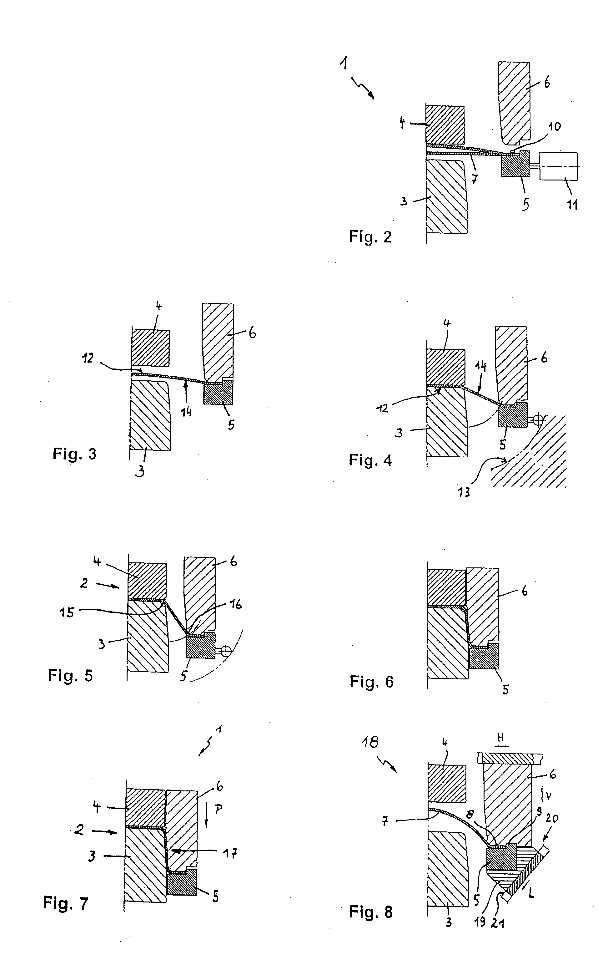
[0020]Throughout all the Figures, same or corresponding elements may generally be indicated by same reference numerals. These depicted embodiments are to be understood as illustrative of the invention and not as limiting in any way. It should also be understood that the figures are not necessarily to scale and that the embodiments are sometimes illustrated by graphic symbols, phantom lines, diagrammatic representations and fragmentary views. In certain instances, details which are not necessary for an understanding of the present invention or which render other details difficult to perceive may have been omitted.

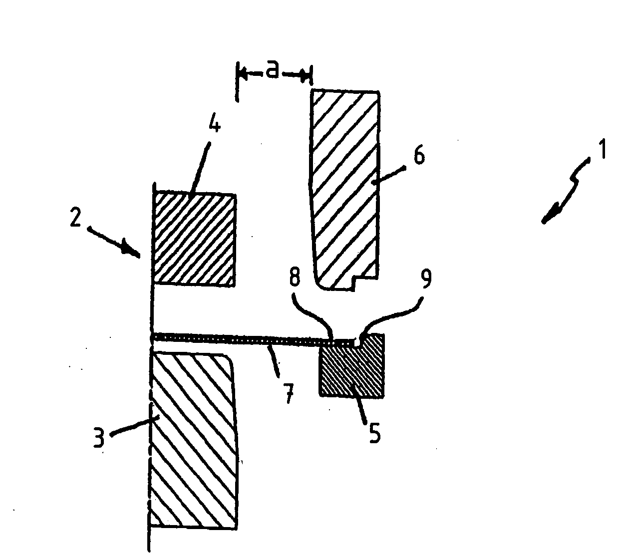
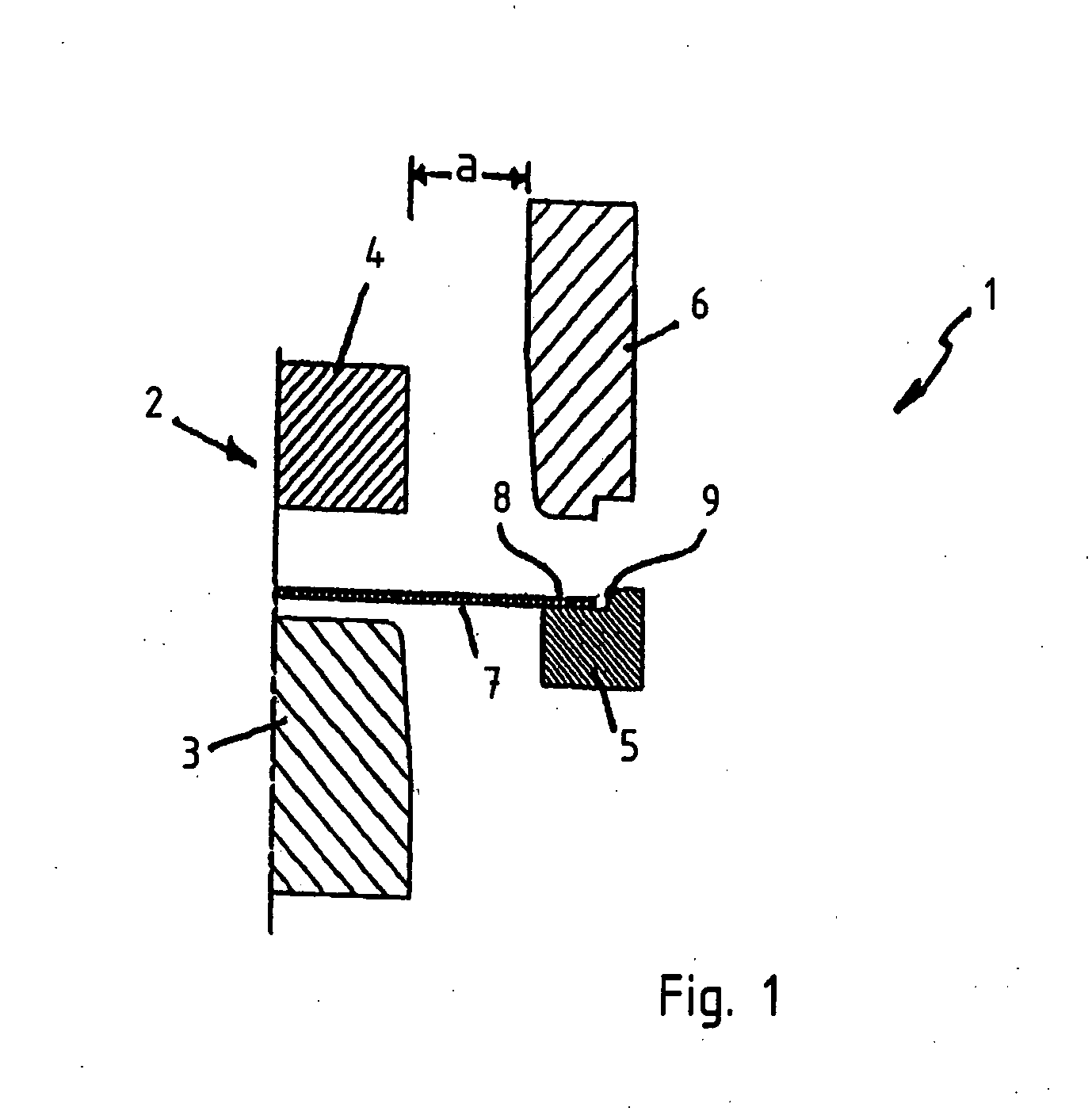
[0021]Turning now to FIGS. 1-7, there are illustrated schematically, in cross section, a die, generally designated by reference numeral 1, for carrying out a process of making a sheet metal part in accordance with the present invention. For convenience and sake of simplicity, the following description is made only in relation to one side of the die 1 (here the right side), w...


PUM

PropertyMeasurementUnit
temperaturesaaaaaaaaaa
lengthaaaaaaaaaa
joint movementaaaaaaaaaa

Abstract

In a method of making a sheet metal part for motor vehicles, a blank is placed with its opposite length sides between outer lower forming jaws of a die. The blank is then clamped by moving the outer lower forming jaws toward one another. Outer upper forming jaws are then moved to their closed position so that the length sides of the blank are secured in place between the lower and upper forming jaws. The lower and upper forming jaws and a press tool are then moved toward one another, and the blank is shaped to its final configuration to produce a sheet metal part.

Description

CROSS-REFERENCES TO RELATED APPLICATIONS[0001]This application claims the priority of German Patent Application, Serial No. 10 2006 040 893.4, filed Aug. 31, 2006, pursuant to 35 U.S.C. 119(a)-(d), the content of which is incorporated herein by reference in its entirety as if fully set forth herein.BACKGROUND OF THE INVENTION[0002]The present invention relates to a method of making a sheet metal part for motor vehicles.[0003]Nothing in the following discussion of the state of the art is to be construed as an admission of prior art.[0004]Heretofore, sheet metal parts for motor vehicles, also of relatively uniform profile and slight curves, with or without blank holders, are produced on a large scale using drawing or press forming processes. This is applicable for cold forming as well as press hardening of the sheet metal parts which are hot formed in a cooled die at initial temperatures of above 900° C. and then allowed to cool down in the die to harden.[0005]As the advance of the bl...

Claims


Application Information

Patent Timeline
Patent Type & Authority Applications(United States)
IPC IPC(8): B21D22/22
CPCB21D22/22B21D25/00B21D24/04
Inventor KNAUP, HANS-JURGEN
Owner BENTELER AUTOMOBILTECHNIK GMBH
Why Eureka
Eureka Blog
Learn More