Device for driving the rotor of turbine engine auxiliary
- Summary
- Abstract
- Description
- Claims
- Application Information
AI Technical Summary
Benefits of technology
Problems solved by technology
Method used
Image

Examples
Embodiment Construction
[0033]In the various embodiments depicted, elements that are common are denoted by the same references.
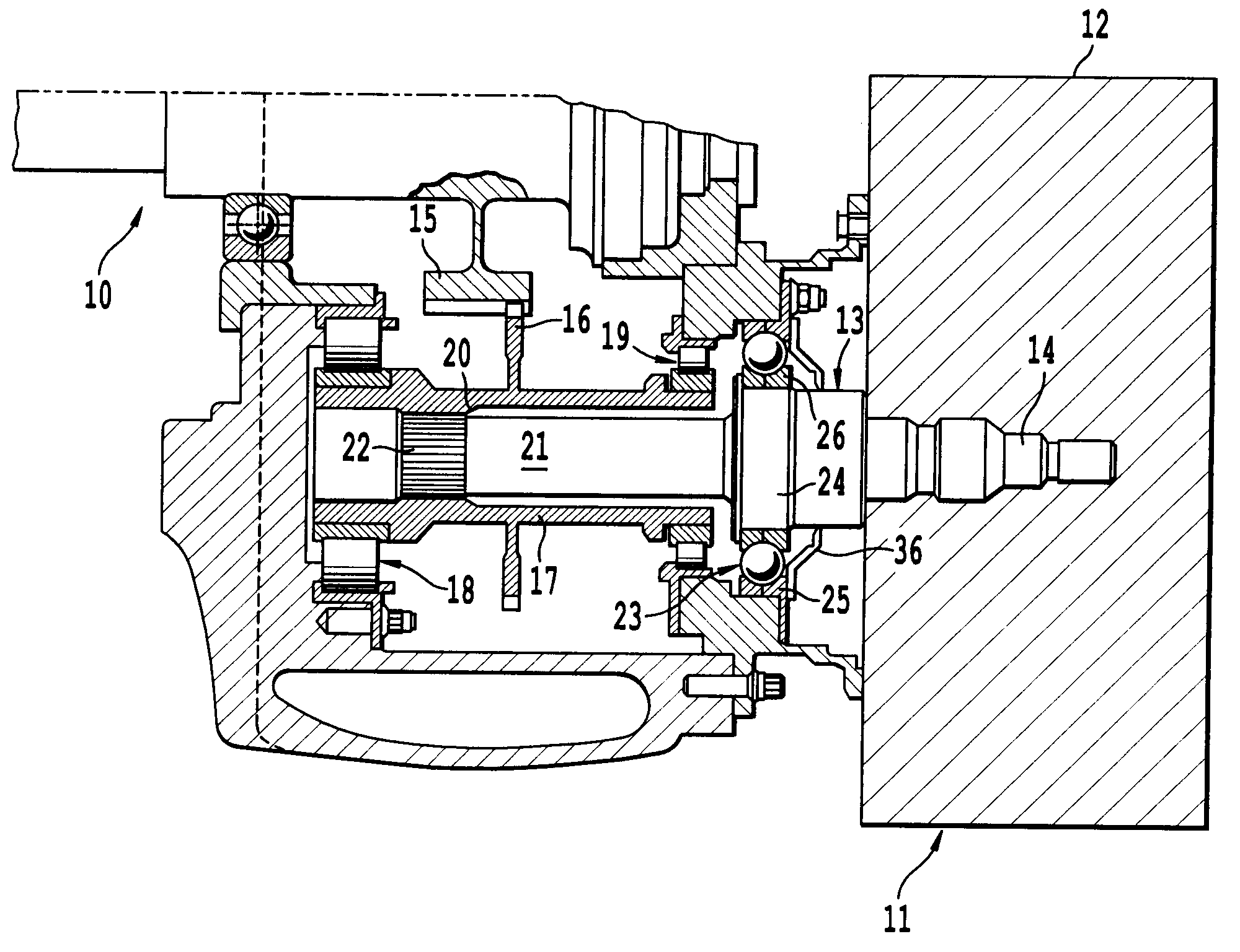
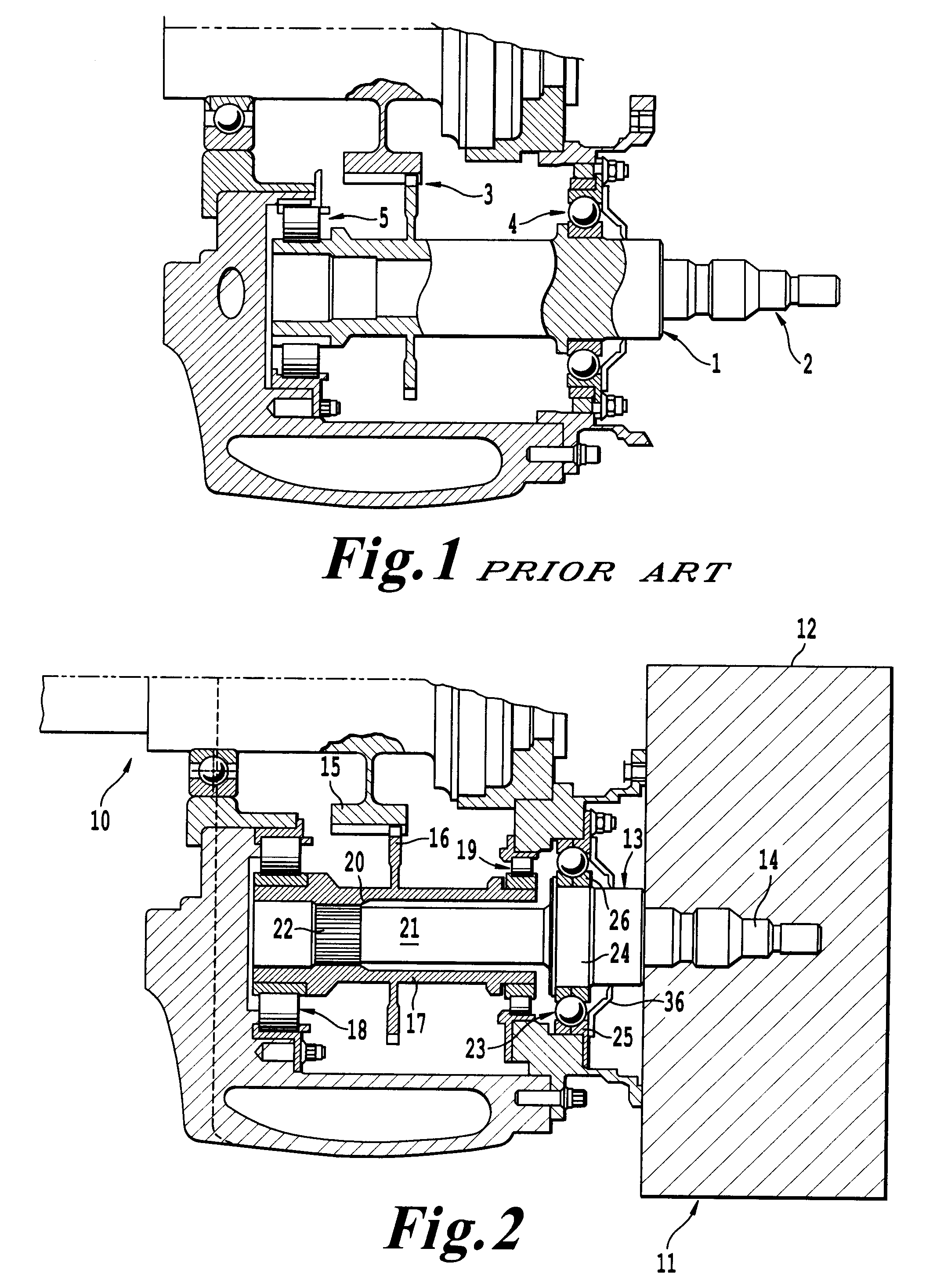
[0034]With reference to FIG. 2, a turbojet comprises an auxiliaries support 10, or accessory drive gearbox assembly 10, for which the abbreviation, well known to those skilled in the art, is AGB, and as outlined above, hereinafter termed gearbox 10. The gearbox 10 is fixed to the periphery of the turbojet; for example, in the case of a bypass turbojet, it is fixed to the outer casing of its fan. The turbojet comprises, on the high-pressure shaft, power take-off means meshing with a shaft connected to the gearbox 10, which will be termed the power take-off shaft. This shaft, which therefore extends radially between the high-pressure shaft of the turbojet and the gearbox 10, is inserted inside the latter and mechanically drives a number of auxiliaries, or accessories, including an alternator 11 for the FADEC device, fuel and oil pumps, a starter, an alternator that generates electric...
PUM
 Abstract
Description
Claims
Application Information