Seebeck Solar Cell

Inactive Publication Date: 2008-03-06
MICALLEF JOSEPH A
View PDF7 Cites 26 Cited by
  • Summary
  • Abstract
  • Description
  • Claims
  • Application Information

AI Technical Summary

Benefits of technology

[0008]A Seebeck solar cell device is disclosed, combining both photovoltaic and thermoelectric techniques in an efficient and powerful way. The device may be formed using, for example, a conventional photovoltaic cell formed from a doped silicon wafer. The material used to form conductors (e.g., contacts or leads) to the front and rear regions of the cell are chosen for their thermoelectric characteristics, including the sign, or polarity, of their Seebeck coefficients. More specifically, a first material having a negative Seebeck coefficient is used to form a conductor to the n-type region of the cell and a second mat

Problems solved by technology

Alternative energy sources are being given renewed attention due to the high price of oil, environmental concerns associated with hydrocarbon-based technologies and political instability in oil producing areas of the world.
A great deal of time and effort has been spent researching how best to convert the sun's energy into power usable in modern society.
But photovoltaic cells suffer from significant limitations of efficiency.
One reason for the inefficiency is the inability of low energy photons to move valence band electrons to the conduction band in the conventional materials used in modern photovoltaic cells.
And while research continues into better materials capable of converting more of the available solar energy to electricity, to date only minimal progress has been made in that direction.
However, once it was determined that conventional materials possessed only relatively low “figures of merit”—and therefore could create only very small thermoelectric voltages—interest in the phenomenon diminished.
And while more recently interest in developing new materials having higher figures of merit has increased, the successful exploitation of the Seebeck effect in power generation has been very limited.
Combinations of photovoltaic and thermoelectric technology have been attempted in the past, with little or no success.
It appears that prior attempts to combine both technologies have not created sufficient power to justify the added expense such systems required, or perhaps simply did not work.

Method used


Image

  • Seebeck Solar Cell
  • Seebeck Solar Cell
  • Seebeck Solar Cell

Examples


Embodiment Construction

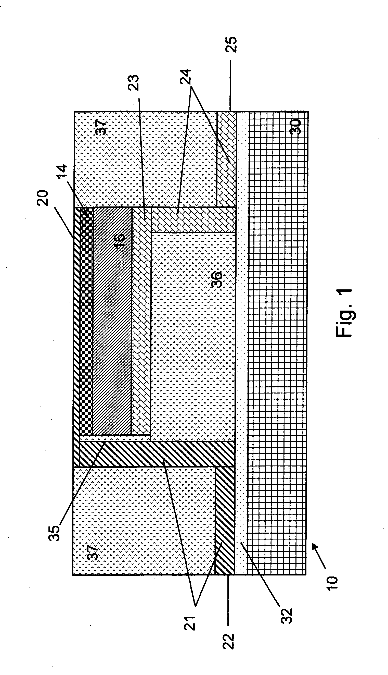
[0011]Referring to FIG. 1, an exemplary device 10 in accordance with the present invention is depicted. In that example a conventional photovoltaic cell is formed by diffusing an n-type dopant into one region 14 of a p-type wafer 16. Region 14 will be referred to here as the “front” of the cell because in this example that is the region most directly exposed to solar radiation. Those of ordinary skill in the art will understand that the commercial manufacture of such a cell will require various additional structures, steps and details not described here, such as deposition of an antireflective coating, sintering, a tempered glass front cover and polymer encapsulation. All of these are well-known to the art and therefore are not described in further detail.

[0012]Front contact 20 is formed in the upper / front (n-type) region and connected to a first electrical lead 21, having lead end 22. The front contact and first lead are formed in a conventional manner, well-known in the art. In pa...


PUM


Abstract

A Seebeck solar cell device is disclosed, combining both photovoltaic and thermoelectric techniques. The device may be formed using, for example, a conventional photovoltaic cell formed from a doped silicon wafer. The material used to form conductors to the front and rear regions of the cell are chosen for their thermoelectric characteristics, including the sign, or polarity, of their Seebeck coefficients. The distal portion of each conductor is insulated from the solar and waste heat and, in some embodiments, is also coupled to a cooling mechanism. Multiple such devices can be connected in series or parallel.

Description

BACKGROUND OF THE INVENTION[0001]Alternative energy sources are being given renewed attention due to the high price of oil, environmental concerns associated with hydrocarbon-based technologies and political instability in oil producing areas of the world. One such potential source of energy is solar power. Another is thermoelectric power.[0002]Solar energy, of course, has been the subject of study and of commercial exploitation for some time. A great deal of time and effort has been spent researching how best to convert the sun's energy into power usable in modern society. While many different techniques have been devised, photovoltaic cells are by far the most common and commercially successful. The operation of a photovoltaic cell is well understood. When the cell is exposed to solar radiation it absorbs photons of a certain energy. The photons transfer energy to electrons in the crystal lattice of the silicon. The transferred energy “excites” the electrons into the conduction ba...

Claims


Application Information

Patent Timeline
IPC IPC(8): H02N6/00H01L35/30H01L31/00
CPCH01L31/0583H02S10/10H01L31/18H01L35/32Y02E10/50H10N10/17
Inventor MICALLEF, JOSEPH A.
Owner MICALLEF JOSEPH A
Why Eureka
Try Eureka