Hibrid vehicle using a hydraulic drive for low speed and an electric drive for high speed.

Inactive Publication Date: 2008-03-06
ONEILL JOHN WILLIAM
View PDF26 Cites 18 Cited by
  • Summary
  • Abstract
  • Description
  • Claims
  • Application Information

AI Technical Summary

Benefits of technology

[0016]The alternating current (AC) drive system is the fourth module. An AC motor's maximum torque is near (induction) or at (synchronies) its' operating frequency. When the AC is developed on board the vehicle, the frequency of the AC can be set as a function of the speed of the vehicle. Therefore the drive motors are always at their best torque at that frequency. When an alternator is used with a mechanical constant power source, it has a great advantage over the direct current (DC) drive systems commonly used in hybrids. That advantage is the large current used to drive the high speed system can be controlled by adjusting the relatively small alternator field current. When solid state power amplifiers are used with a fuel cell, the current is controlled by individual power amplifiers for each AC motor field pole (about 24). The unique design of either AC drive systems eliminates the requirement for an expensive “Controller” presently used on all commercially available hybrids.
[0018]The modular construction is the greatest advantage over the present vehicle drive systems. Each module (power storage, hydraulic drive, constant power source and AC drive) require different types of expertise. Each discipline of engineering can work independently on increasing the efficiency of their module while decreasing the size and weight. The common goal is to use less fuel.

Problems solved by technology

Most commercially available hybrid vehicles boast of an unlimited range but require large heavy engines and heavy expensive batteries.

Method used


Image

  • Hibrid vehicle using a hydraulic drive for low speed and an electric drive for high speed.
  • Hibrid vehicle using a hydraulic drive for low speed and an electric drive for high speed.
  • Hibrid vehicle using a hydraulic drive for low speed and an electric drive for high speed.

Examples


Embodiment Construction

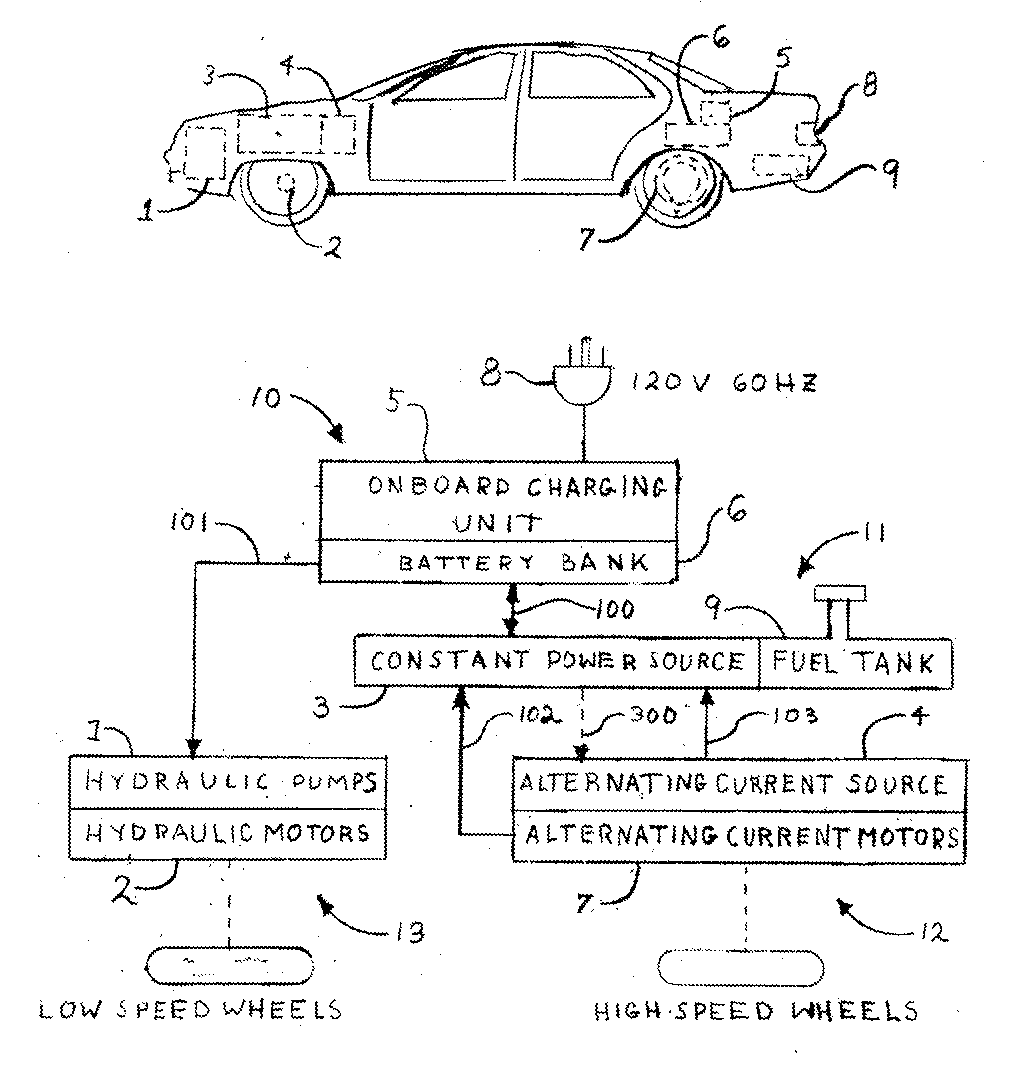
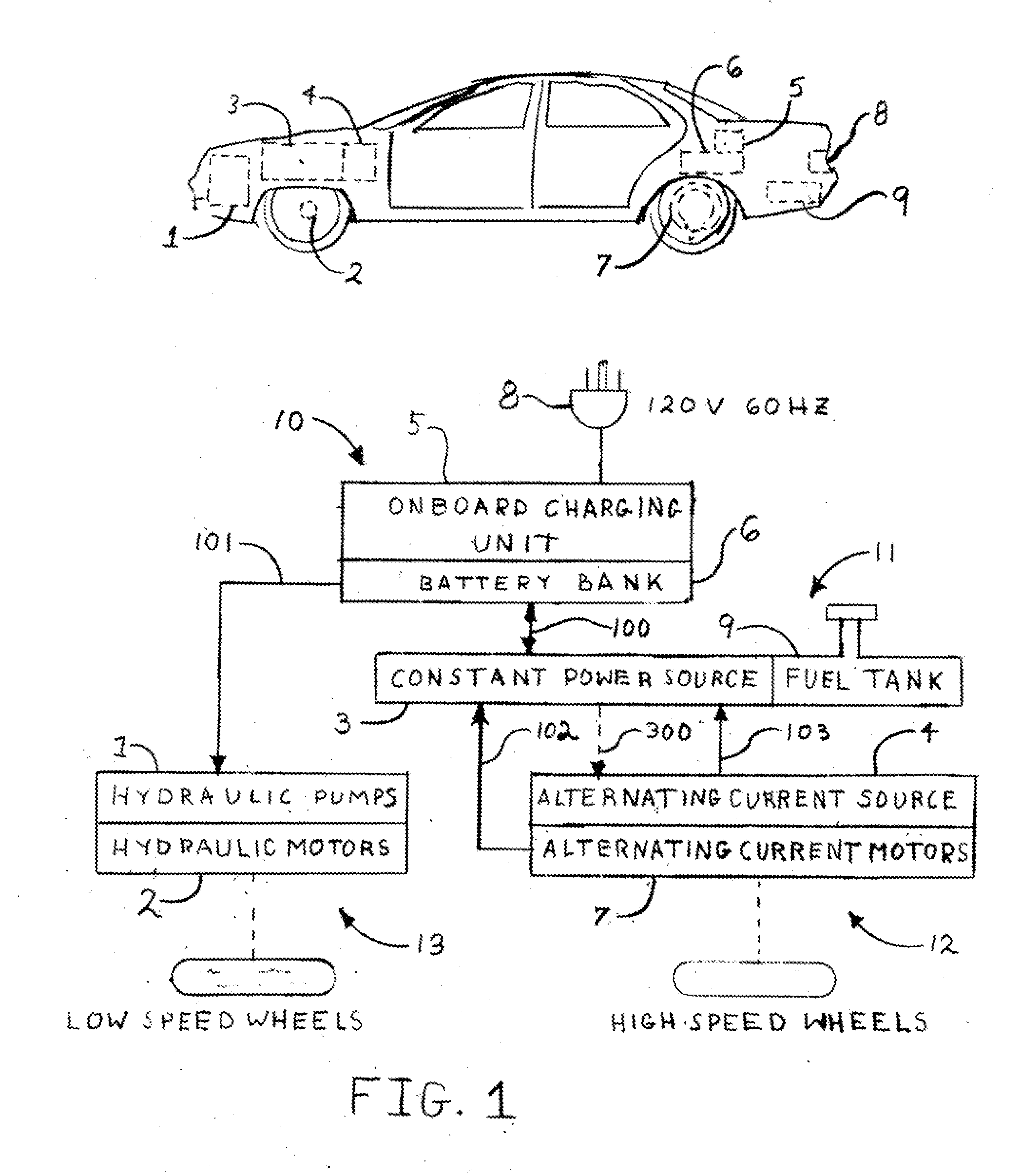
[0026]The pictorial potion of FIG. 1 is a notional depiction of an existing chassis with the conventional front wheel drive system removed and the invented systems installed. The hydraulic motors 2 are mounted on the front wheels were the drive shafts were removed. The hydraulic pumps and controls 1 are located in the engine compartment forward of the front wheels. The constant power source 3 and the alternating current source 4 are located in the space vacated by the conventional combustion engine and transmission. The battery bank 6 and onboard charger 5 are located behind the rear seat. The alternating current motors 7 are located between the oversized tire rims and the brakes. The power receptacle 8, for externally charging the batteries, is located behind a spring loaded number plate bracket. The existing fuel tank 9 is used for liquid fuel applications but must be replaced for hydrogen. Again the pictorial is a notional arrangement to an existing chassis, the component locatio...


PUM


Abstract

A hybrid electric vehicle with two separate drive systems. Low speed operation is powered by hydraulic motors directly coupled to the drive wheels. The hydraulic oil is pressurized by direct current motors energized by a battery pack. High speed operation is powered by poly phased alternating current motors with-in the wheel rims. The alternating current motors are energized by mechanical or electronically generated alternating current. The hybrid power source is either a combustion engine driving an alternator or a fuel cell providing direct current. In the case of the combustion engine, a helper direct current motor / generator will augment the engine with power from the battery pack under large demands and charge the battery pack under small demands. In the case of a fuel cell, the cell is augmented by the battery pack under large demands and charges the battery pack under small or no demands.

Description

CROSS-REFERENCE TO RELATED APPLICATIONS[0001]U.S. Patent documents5697466December 1997Moroto, et. al.180 / 65.26048289April 2000Hottori, et. al.477 / 156719080April 2004Gray180 / 1656823954November 2004Skimabukuro, et. al.180 / 65.26945345September 2005Meaney180 / 65.26959545November 2005Lippert 60 / 4307011051March 2006Epshteyn123 / 46R7041030May 2006Kuroda, et. al.477 / 21STATEMENT REGARDING FEDERALLY SPONSORED R & D[0002]NoneREFERENCE TO A SEQUENCE LISTING, ETC[0003]NoneBACKGROUND OF THE INVENTION[0004]1. Field of the Invention[0005]The invention relates to hybrid vehicles having a fuel consuming source of power and a power storage unit. The vehicle is primarily driven by the power storage unit at low speeds and the fuel consuming unit at high speeds with the ability of using both the fuel consuming source of power and the power storage unit for extended low or high speed operation. The invention also relates to different types of fuel sources for power. The fuel ranges from conventional gas / die...

Claims


Application Information

Patent Timeline
IPC IPC(8): B60K6/00
CPCB60K6/12Y02T10/648B60K6/52B60K7/0015B60L11/005B60L11/02B60L11/123B60L11/1816B60L11/1877B60L11/1887Y02T10/6208Y02T10/6217Y02T10/6265Y02T10/6269Y02T10/6282Y02T10/646Y02T10/7005Y02T10/7022Y02T10/705Y02T10/7077Y02T90/14Y02T90/34B60K6/46B60L50/10B60L50/40B60L50/61B60L50/66B60L53/14B60L58/40Y02T10/62Y02T10/70Y02T10/7072Y02T10/64Y02T90/40
Inventor O'NEILL, JOHN WILLIAM
Owner ONEILL JOHN WILLIAM
Why Eureka
Try Eureka