Electroacoustic transducer and diaphragm

Inactive Publication Date: 2008-03-06
VICTOR CO OF JAPAN LTD
View PDF12 Cites 40 Cited by
  • Summary
  • Abstract
  • Description
  • Claims
  • Application Information

AI Technical Summary

Benefits of technology

[0033] Still another aspect of the present invention inheres in a diaphragm encompassing a center vibrating portion having a substantial dome shape in a cross section; and an outer circumferential vibrating portion having a substantial dome shape in the cross section and formed over an entire outer circumference of the center vibrating portion, wherein the center vibrating portion and the outer circumferential vibrating portion including: a first area including an entirety of the center vibrating portion; and second area including the edge portion of the outer circumferential vibrating portion, having flexibility, and formed of a material softer than a material of the first area.
[0034] Still another aspect of the present invention inheres in a dia

Problems solved by technology

As described above, in the diaphragm of the full-range type, the problems occur particularly from the midrange band to the treble band.
However, in JP 2002-152885, which improves the midrange band, there are malfunctions that it is necessary to use such a special material with the internal loss characteristics of 0.02 or more.
Moreover, adoption of JP 2002-152885 does not result very much in an improvement of audio frequency band other than the treble band.
Furthermore, JP 2002

Method used


Image

  • Electroacoustic transducer and diaphragm
  • Electroacoustic transducer and diaphragm
  • Electroacoustic transducer and diaphragm

Examples


first embodiment

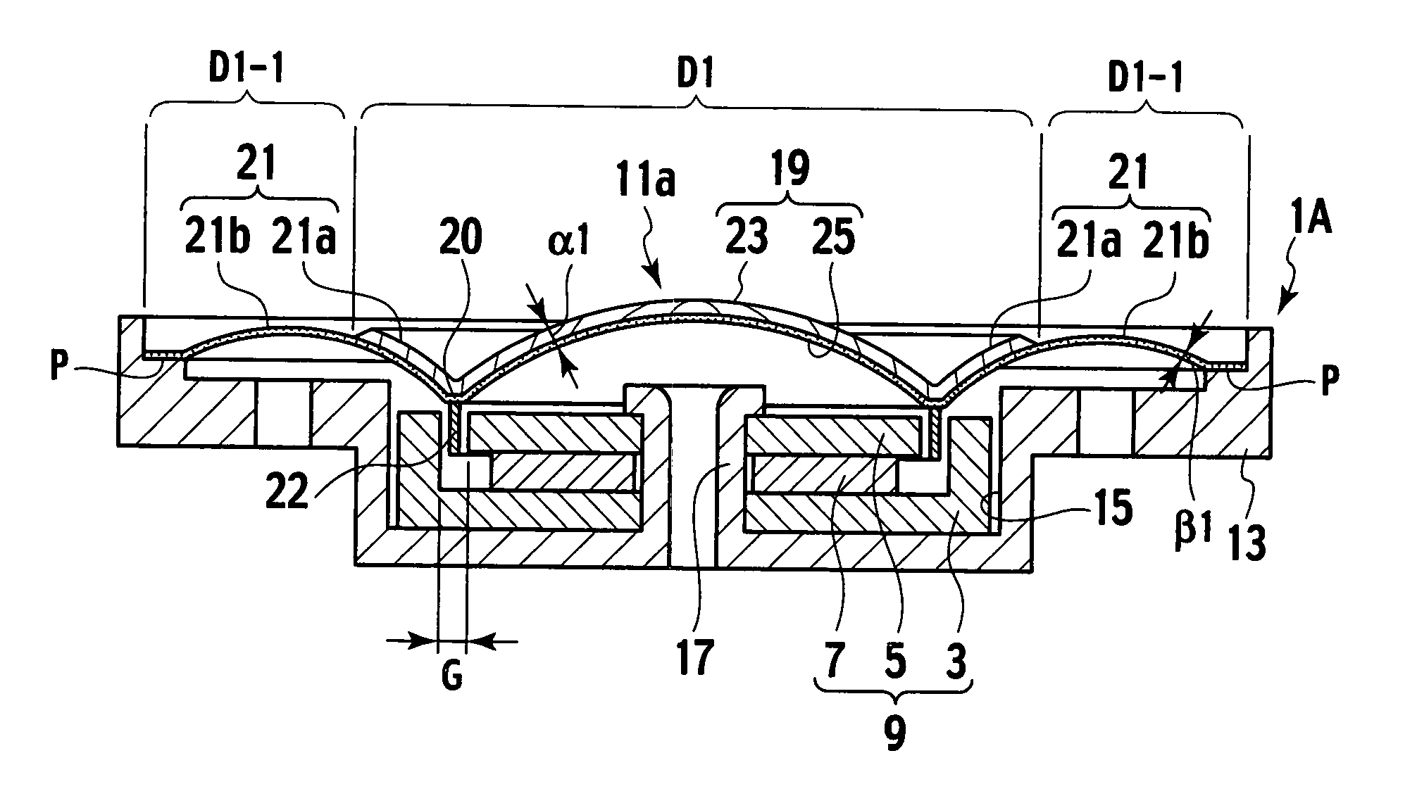
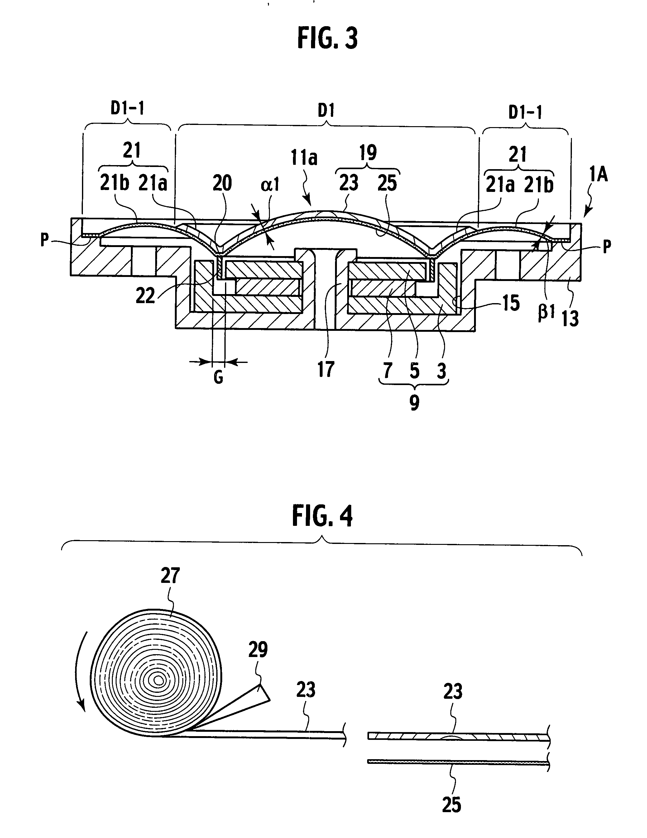
[0058] As shown in FIG. 3, an electroacoustic transducer 1A according to a first embodiment of the present invention includes: a magnetic circuit 9 including a magnetic pole (yoke) 3, a center pole 5, and a magnet 7; and a diaphragm 11a disposed above the magnetic circuit 9.

[0059] The magnetic pole 3, the center pole 5, and the magnet 7 are fitted to a columnar protrusion 17 erected from a recessed portion 15 of a frame 13, and are enclosed in the recessed portion 15 while having a predetermined gap G between the magnetic pole 3 and the center pole 5.

[0060] The diaphragm 11a includes: a center vibrating portion 19 having a substantial dome shape in cross section; and an outer circumferential vibrating portion 21 formed to be integrally continuous with an outer circumference of the center vibrating portion 19. Onto a back surface of the diaphragm 11a, which becomes a coupling portion 20 continuous from the center vibrating portion 19 to the outer circumferential vibrating portion 2...

second embodiment

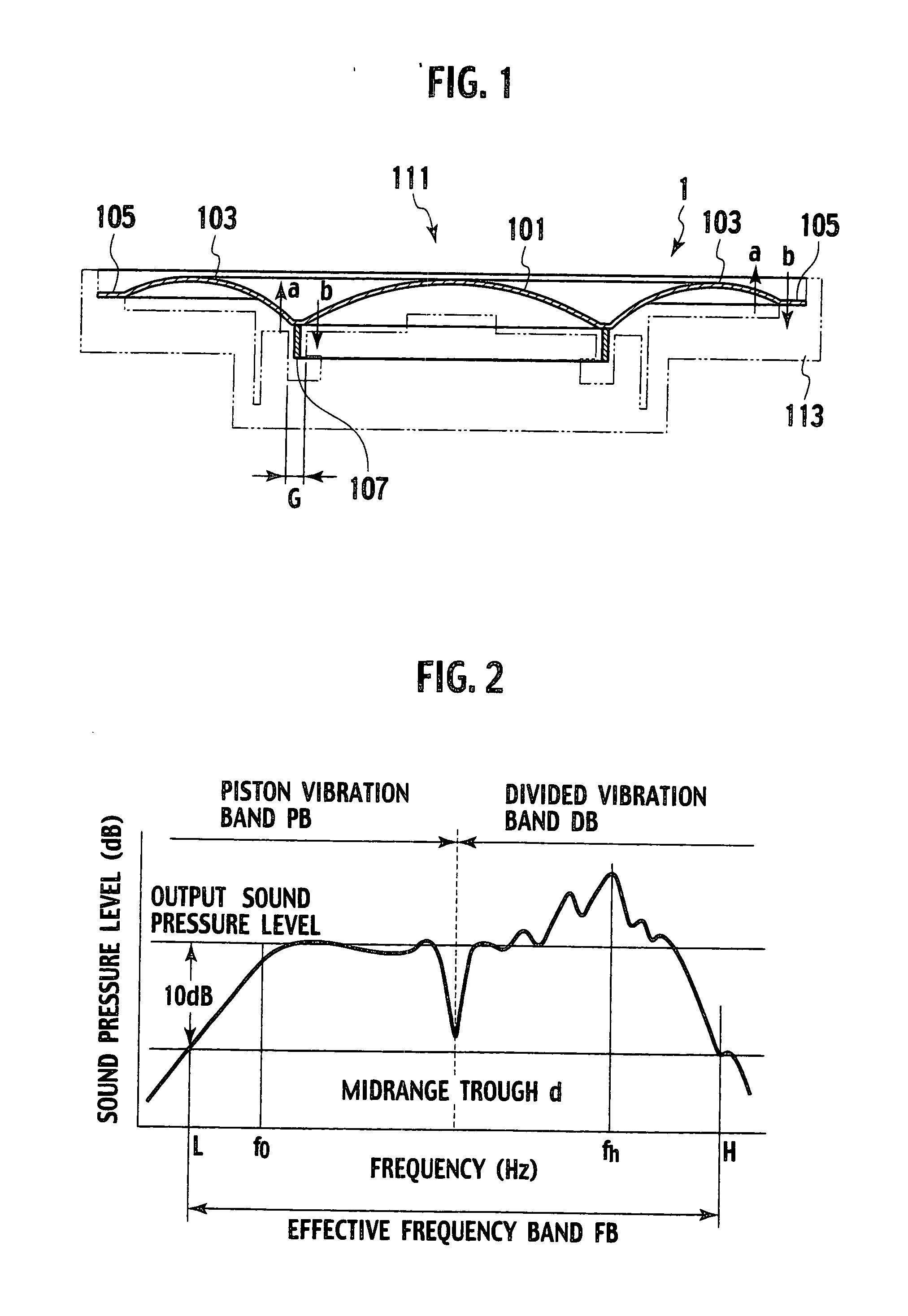
[0075] As shown in FIG. 8, an electroacoustic transducer 1B according to a second embodiment is different from the electroacoustic transducer 1 shown in FIG. 1 in including a diaphragm 11c.

[0076] The diaphragm 11c includes: the center vibrating portion 19 having a substantial dome shape in cross section; and the outer circumferential vibrating portion 21 having a substantial dome shape in cross section, which is formed on the outer circumference of the center vibrating portion 19. The diaphragm 11c has a shape in which the center vibrating portion 19 is integrally continuous with the outer circumferential vibrating portion 21 by the coupling portion 20. Onto a back surface of the coupling portion 20, a voice coil 22 is joined and supported through the adhesive while being centered by the drop-in in the gap G. Meanwhile, the outer circumferential vibrating portion 21 is composed of a plate portion 21a with the same thickness as that of the center vibrating portion 19, and the edge p...

third embodiment

[0101] As shown in FIG. 12, an electroacoustic transducer 1C according to a third embodiment is different from the electroacoustic transducer 1 shown in FIG. 1 in including a diaphragm 11f.

[0102] The diaphragm 11f includes: the center vibrating portion 19 having a substantial dome shape in cross section; and the outer circumferential vibrating portion 21 formed to be integrally continuous with the outer circumference of the center vibrating portion 19. Onto a back surface of a boundary T continuous with the outer circumferential vibrating portion 21 from the center vibrating portion 19, the voice coil 22 is joined and supported through the adhesive while being centered by the drop-in in the gap G. Meanwhile, the outer circumferential vibrating portion 21 includes the plate portion 21a with the same thickness as that of the center vibrating portion 19, and of the edge portion 21b with a plate thickness thinner than the thickness of the plate portion 21a. A support structure is adopt...


PUM


Abstract

An electroacoustic transducer includes a magnetic circuit; a frame enclosing the magnetic circuit; and a diaphragm including a center vibrating portion and an outer circumferential vibrating portion, the diaphragm comprising: a first plate thickness area including an entirety of the center vibrating portion, having a double-layer structure of a wood sheet and a reinforcement sheet; and a second plate thickness area including the edge portion of the outer circumferential vibrating portion, having a plate thickness thinner than a thickness of the first plate thickness area, and having a single-layer structure of the reinforcement sheet.

Description

CROSS REFERENCE TO RELATED APPLICATIONS AND INCORPORATION BY REFERENCE [0001] This application is based upon and claims the benefit of priority from the prior Japanese Patent Applications No. P2006-234269, P2006-234272, and P2006-234278 filed on Aug. 30, 2006, P2007-152576 and P2007-152577 filed on Jun. 8, 2007, and P2007-157835 filed on Jun. 14, 2007; the entire contents of which are incorporated herein by reference. BACKGROUND OF THE INVENTION [0002] 1. Field of the Invention [0003] The present invention relates to a diaphragm, and a full-range electroacoustic transducer including headphones and the like. [0004] 2. Description of the Related Art [0005] In recent years, one using natural wood as a raw material of a diaphragm has been known. The reason to use the wood as the raw material of the diaphragm is that natural timbre intrinsic to the wood is obtained in addition to that the wood has comprehensively excellent characteristics. For example, the wood has higher acoustic veloci...

Claims


Application Information

Patent Timeline
IPC IPC(8): G10K13/00H04R1/00
CPCH04R1/10H04R7/127H04R5/033H04R1/24
Inventor TADA, TAKUMUISEKI, TAKAYUKIHIROSE, SHINICHISUZUKI, YOSHIAKI
Owner VICTOR CO OF JAPAN LTD
Why Eureka
Try Eureka