Noise suppressor, electronic apparatus, and noise suppression characteristic control method

Active Publication Date: 2008-03-06
SHARP NEC DISPLAY SOLUTIONS LTD
View PDF13 Cites 29 Cited by
  • Summary
  • Abstract
  • Description
  • Claims
  • Application Information

AI Technical Summary

Benefits of technology

[0075]The noise suppressor of the present invention may obtain the effect of suppressing the radiation of fan noise by arranging a reflection plate at a position that may be substantially parallel to the fan intake plane inside a cooling duct and prescribing the distance between this fan intake plane and reflection plate within a region in which a near field may be formed in which the radiation power of fan noise is localized only in the vicinity of the sound source, and may raise the efficiency of introduction of fan noise to the muffler to enable an improvement in the sound absorption coefficient by forming a muffler constituted by a Helmholtz resonator, a panel sound absorber, or a membrane sound absorber from a reflection plate and an air chamber that may be formed on the opposite side of the reflection plate and providing this sound absorber part on the reflection plate. Accordingly, the present invention may have the effect of enabling a sound absorbi

Problems solved by technology

The present invention may achieve quieter operation than related art noise suppressors by using a large fan that operates at low revolutions results in an increase in the installation volume of the fan and interferes with miniaturization of the device.
Securing area for the passage of air in the duct therefore becomes problema

Method used


Image

  • Noise suppressor, electronic apparatus, and noise suppression characteristic control method
  • Noise suppressor, electronic apparatus, and noise suppression characteristic control method
  • Noise suppressor, electronic apparatus, and noise suppression characteristic control method

Examples


first embodiment

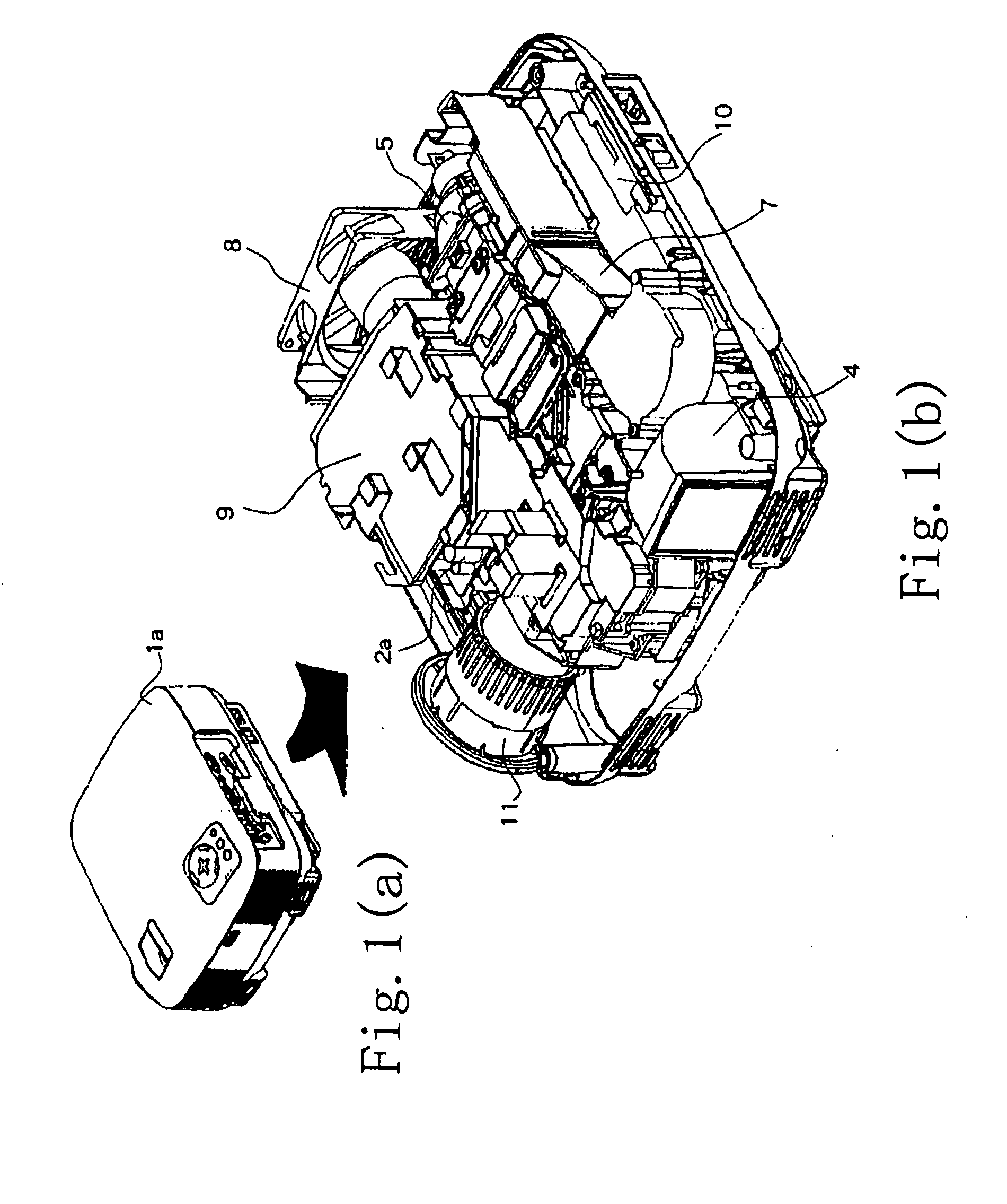
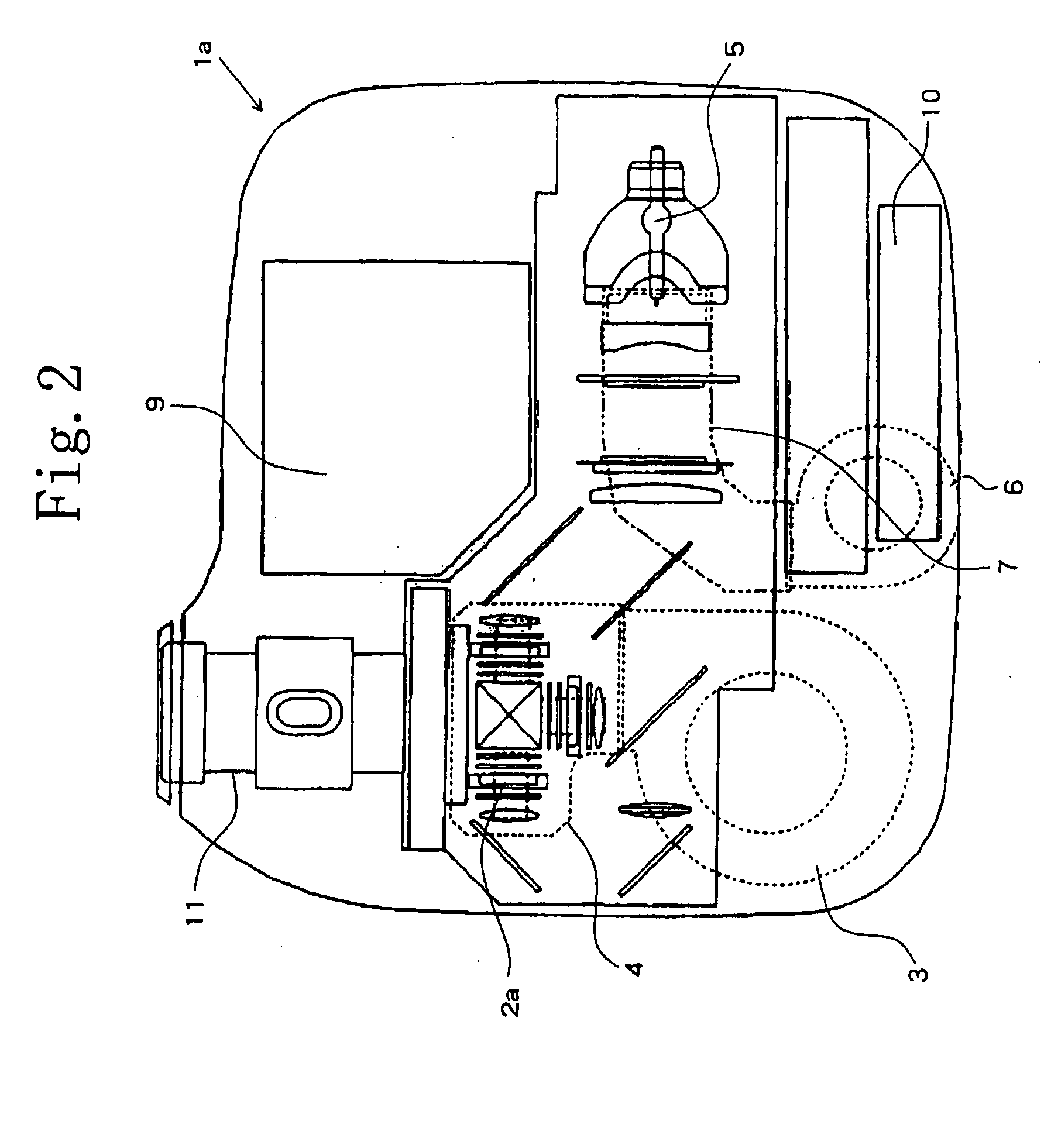
[0117]FIGS. 16(a)-16(c) are explanatory views of the noise suppressor of the present invention, FIG. 16(a) showing a schematic perspective view of an electronic apparatus (liquid crystal projector) in which the noise suppressor of the present invention may be installed, the cover of the electronic apparatus being removed, FIG. 16(b) is an exploded perspective view in which only the noise suppressor portion (cooling duct) has been removed from the electronic apparatus (liquid crystal projector) in which the noise suppressor of the present invention has been installed, and FIG. 16(c) is a rear view of the noise suppressor (cooling duct) of the present invention as seen from the side of the cooling fan.

[0118]FIG. 17 is an exploded perspective view for explaining the configuration of the cooling duct portion in the first embodiment of the noise suppressor of the present invention.

[0119]FIG. 18 is a schematic sectional view for explaining the internal configuration and the ventilating op...

third embodiment

[0134]The following explanation regards the noise suppressor of the present invention while referring to the accompanying figures.

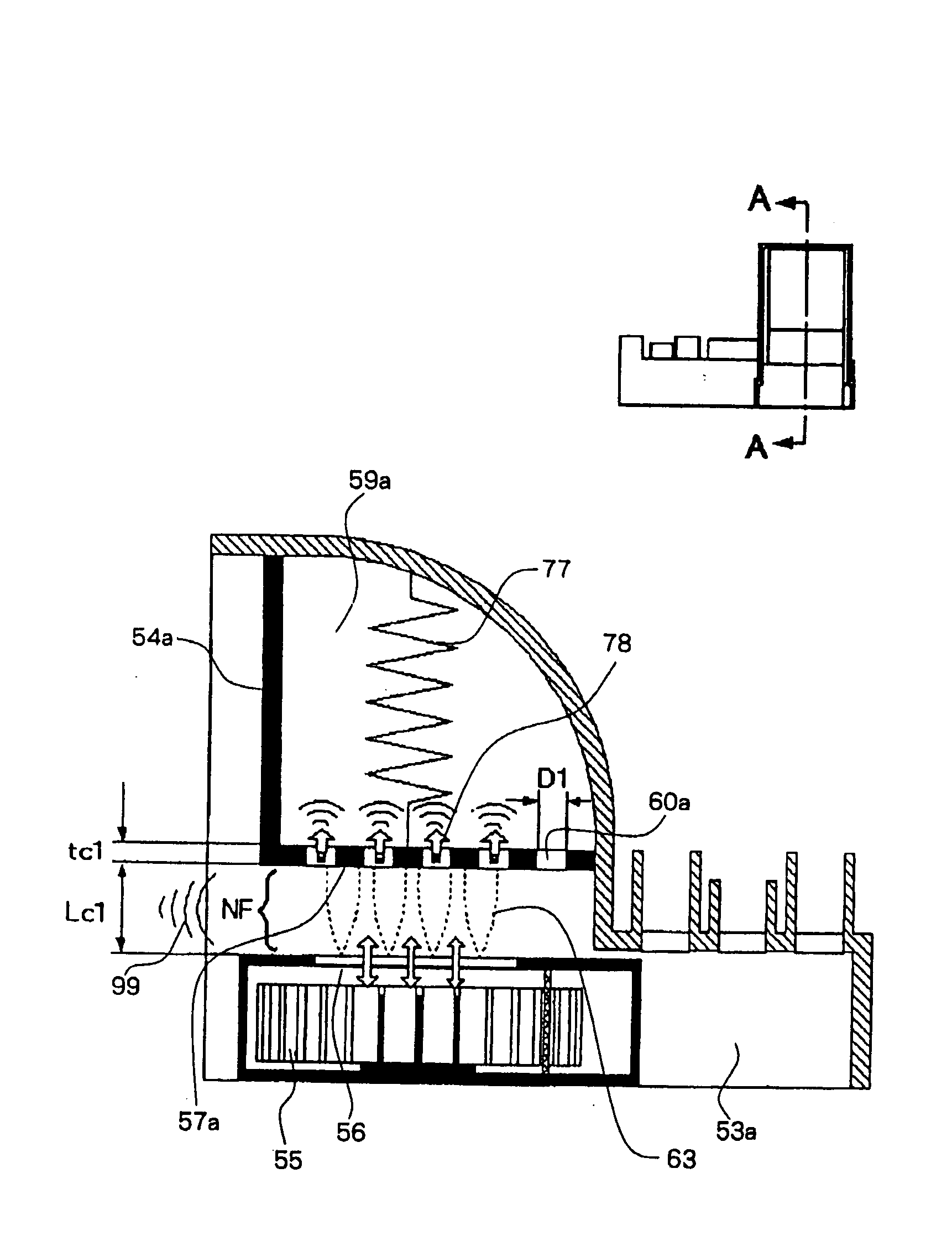
[0135]FIGS. 22(a)-22(d) are explanatory views of the noise suppressor of the third embodiment of the present invention, FIG. 22(a) being a schematic perspective view for explaining the configuration of the cooling duct, FIG. 22(b) and FIG. 22(c) being schematic perspective views for explaining the configuration of the added wall part of L shape that forms the sound absorber in the cooling duct, and FIG. 22(d) being a schematic sectional view for explaining the configuration of the sound absorber in the cooling duct. In addition, FIG. 23 is a schematic sectional view for explaining the sound-absorbing operation in the cooling duct in the third embodiment of the noise suppressor of the present invention.

[0136]Noise suppressor 52c in the present embodiment may be of a configuration in which muffler 54a provided in the cooling duct in the first embodiment may...


PUM


Abstract

A noise suppressor for an apparatus having a cooling fan and cooling duct includes a muffler including a reflection plate for reflecting sound from the cooling fan, the reflection plate being provided at a position in the cooling duct confronting the intake plane of the cooling fan and formed substantially parallel to the intake plane. A sound-absorbing part of the muffler is provided on the reflection plate, and a distance d between the reflection plate and the intake plane is set such that d<c/(2×f) where f is the sound-absorption frequency of the muffler and c is the speed of sound.

Description

[0001]This application is based upon and claims the benefit of priority from Japanese patent application No. 2006-232166, filed on Aug. 29, 2006, the disclosure of which is incorporated herein its entirely by reference.BACKGROUND OF THE INVENTION[0002]1. Field of the Invention[0003]The present invention relates to a noise suppressor used in an apparatus having a cooling fan and a cooling duct, to an electronic apparatus provided with a noise suppressor, and to a method of effectively controlling the noise suppression characteristics of these devices, and more particularly, relates to a noise suppressor and method for effectively suppressing the noise of a cooling fan used in a projection display device such as a liquid crystal projector.[0004]2. Description of the Related Art[0005]Projection display devices that enlarge and project upon a screen images generated on image display elements are becoming widely used not only in the workplace but also in typical homes. Among such project...

Claims


Application Information

Patent Timeline
IPC IPC(8): G10K11/172G10K11/16
CPCG03B21/16
Inventor UTSUNOMIYA, MOTOYASU
Owner SHARP NEC DISPLAY SOLUTIONS LTD
Why Eureka
Try Eureka