Methods And Apparatus For Removing Solids From A Membrane Module

Active Publication Date: 2008-03-06
EVOQUA WATER TECH LLC
99 Cites 38 Cited by

AI-Extracted Technical Summary

Problems solved by technology

In a system exposed to a feed containing a high concentration of solids, the fouling occurs more quickly and more severely, in particular, where membranes are densely packed in a module.
The limitation to this method is the membrane pore size.
Backwash of membranes with permeate has no limitations to the pore size, but the backwash efficiency is generally lower than gas backwash and the transmembrane pressure (TMP) recovery is not enough to offset the fouling rate.
How...

Method used

[0039] 3. Rack inserts containing sets of membrane modules can be lowered down closer to the bottom of the module as an open area is no longer required beneath the modules to accommodate manifold...

Benefits of technology

[0016] The present invention provides for holes or openings in one of the module pots so that during filtration at least part of the feed liquid will also be drawn in through the openings in the bottom pot and flow into the depths of the membrane bundle, reducing shell side pressure drop and generating some crossflow over the membrane surface. The use of these holes or openings for waste flow also allows solids swept along the membranes during the backwash process to continue to flow parallel to the membranes as they exit the module. The requirement for the solids to cross over the fibre bundle to exit ...

Abstract

A method of operating a membrane filtration module (5), the module (5) including one or more membranes (7) extending longitudinally between vertically spaced upper and lower headers (8, 9) into which the ends of the membranes (7) are potted. The membranes (7) have a permeable wall which is subjected to a filtration operation wherein feed containing contaminant matter is applied to one side of the membrane wall and filtrate is withdrawn from the other side of the membrane wall. At least one of the upper and/or lower headers (8, 9) has one or more openings (10) therein and the method including flowing the feed, at least in part, through the one or more openings (10) for application to the membrane wall. Apparatus for performing the method is also disclosed.

Application Domain

Technology Topic

Image

  • Methods And Apparatus For Removing Solids From A Membrane Module
  • Methods And Apparatus For Removing Solids From A Membrane Module
  • Methods And Apparatus For Removing Solids From A Membrane Module

Examples

  • Experimental program(1)

Example

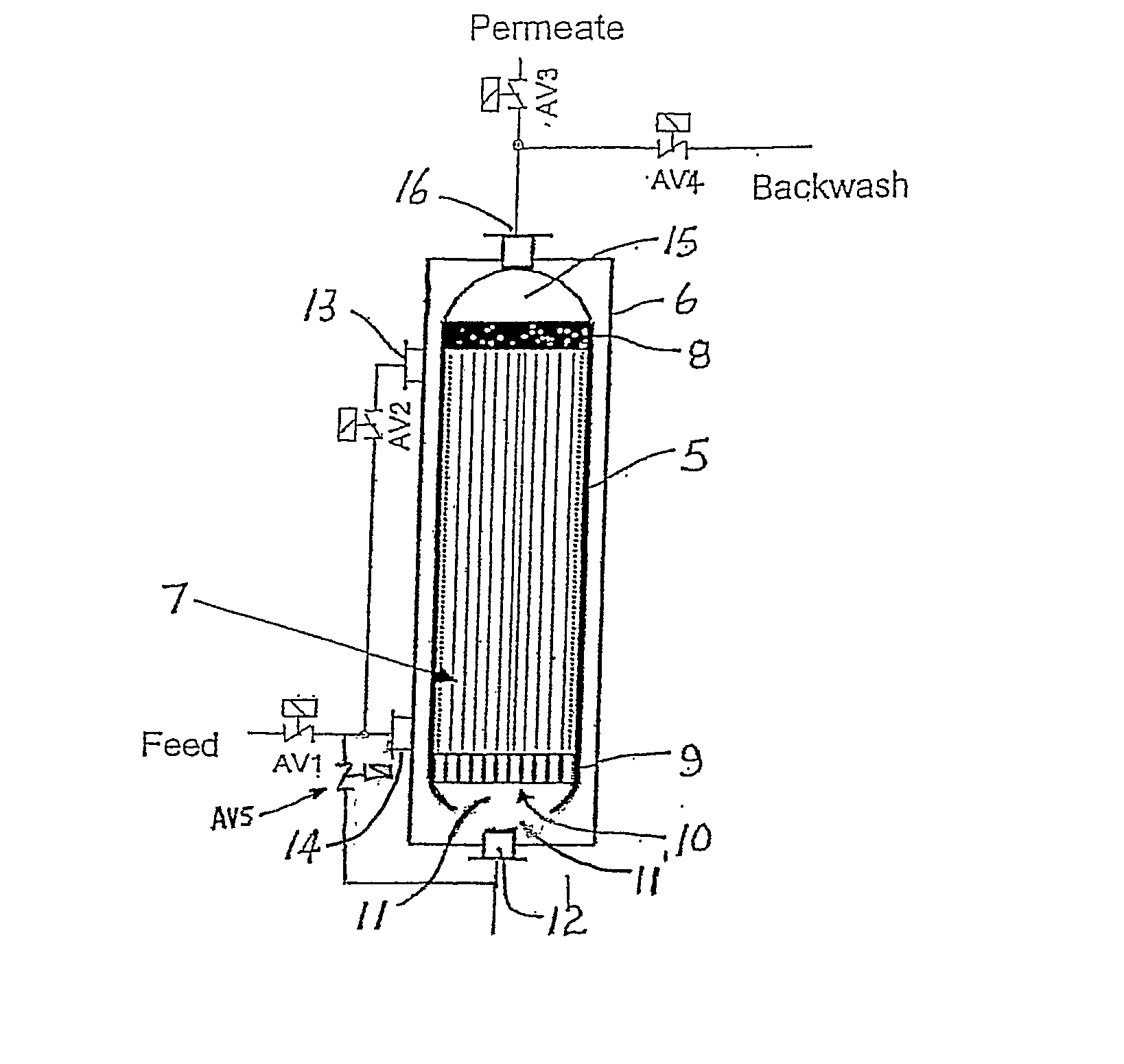
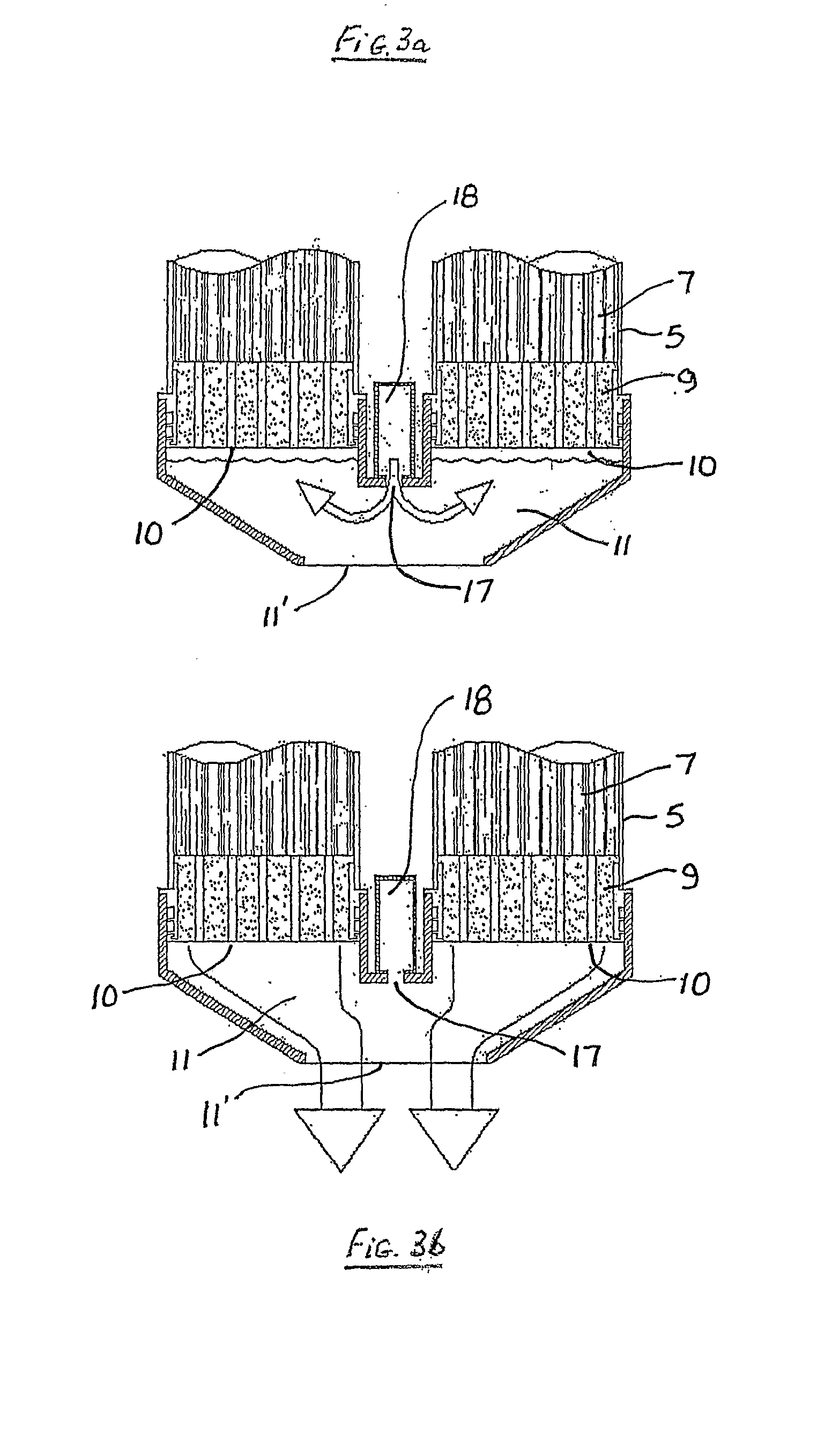
[0030] Referring to the FIG. 1, the filtration module 5 is mounted within a housing vessel 6 which contains the feed to be filtered. The filtration module 5 contains a bundle or bundles of hollow fibre membranes 7 extending between upper and lower headers 8 and 9, respectively. The lower header 9 is provided with a number of openings 10 communicating with the interior of the fibre bundle and an open-ended plenum chamber 11 having an opening 11′. An inlet/outlet port 12 is provided at the base of the module 5. Feed is supplied through ports 12, 13 and 14 under the control of valves AV5, AV1 and AV2.
[0031] Permeate/filtrate is withdrawn through chamber 15 and port 16 under control of valve AV3. A backwash may also be applied through port 16 under the control of valve AV4.
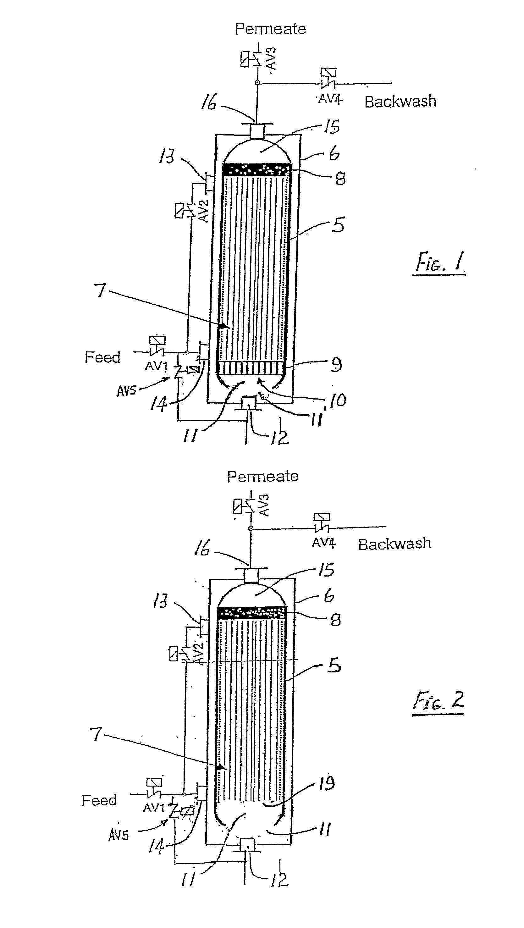
[0032]FIG. 2 shows a similar arrangement to FIG. 1, however, in this embodiment the hollow fibre membranes 7 are suspended vertically from the upper header 8 and are not potted at their lower distal ends 19. The distal ends 19 of each fibre membrane 7 are closed and filtrate withdrawn through the upper header 8.
[0033] In use, solids accumulated within the modules 5 following filtration and backwash are flushed or swept from the modules 5 through the openings 10 by opening port 12 and applying a suitable pressure to the feed within the module 5. The waste is flushed through the opening 11′ in the plenum chamber 11 and removed through open port 12.
[0034]FIGS. 3a and 3b show an enlarged view of the lower headers 9 of a pair of modules 5 connected to a single plenum chamber 11 in a non-pressurized filtration system. The modules 5 in this embodiment are mounted in an open vessel (not shown) and the waste liquid containing solids accumulated within the modules 5 following filtration and backwash is drained through the openings 10 under force of gravity, as shown in FIG. 3b.
[0035] As best shown in FIG. 3a, port 17 connected to a gas supply manifold 18 may also be used to supply gas to openings 10 to provide scouring bubbles within the module 5 to assist cleaning of the fibre membrane surfaces.
[0036] Systems embodying the invention may provide a number of benefits including:
[0037] 1. Enhanced solids removal during backwash due to sweeping action along the fibre surface rather than across multiple fibres.
[0038] 2. Easier contact of feed liquid with the inside of the membrane bundle during filtration (feed liquid can be drawn into the centre of the bundle through the same holes during filtration). This also induces a form of crossflow during filtration.
[0039] 3. Rack inserts containing sets of membrane modules can be lowered down closer to the bottom of the module as an open area is no longer required beneath the modules to accommodate manifolds and piping used for solids removal and feed inlet, this now takes place through the openings in the pot. The result is better void space reduction efficiency as well as less space for drainage.
[0040] 4. The plenum chambers can be connected to a pipe or manifold and the backwash waste pumped out of the module rather then gravity flowed, and/or the feedwater pumped in during filtration.
[0041] It will be appreciated that further embodiments and exemplifications of the invention are possible with departing from the spirit or scope of the invention described.

PUM

PropertyMeasurementUnit
Permeability
Velocity
tensileMPa
Particle sizePa
strength10

Description & Claims & Application Information

We can also present the details of the Description, Claims and Application information to help users get a comprehensive understanding of the technical details of the patent, such as background art, summary of invention, brief description of drawings, description of embodiments, and other original content. On the other hand, users can also determine the specific scope of protection of the technology through the list of claims; as well as understand the changes in the life cycle of the technology with the presentation of the patent timeline. Login to view more.

Similar technology patents

Method for reducing amyloid beta concentration in blood

ActiveUS20120031840A1Efficiently removeSolvent extractionDialysisΒ amyloidRemove blood
Owner:SCHOOL JURIDICAL PERSON FUJITA EDUCATIONAL INSTITUTION +1

Thermal De-Scaling Surfaces With Cryogenic Liquids And Gases

InactiveUS20100132747A1Simplify design and operationEfficiently removeCleaning heat-transfer devicesCleaning apparatusSolid phasesPollutant
Owner:APPLIED CRYOGENIC SOLUTIONS

Classification and recommendation of technical efficacy words

  • Efficiently remove

Hollow fiber membrane module

InactiveUS20070163942A1Efficiently removeFacilitate preventingMembranesSemi-permeable membranesMechanical engineeringHollow fiber membrane
Owner:TORAY IND INC

Anhydrous processing of methane into methane-sulfonic acid, methanol, and other compounds

InactiveUS20080161591A1Increase solubility and reaction rateEfficiently removePeroxyhydrates/peroxyacidsOrganic compound preparationWaste productionSolvent
Owner:RICHARDS ALAN K

System, apparatus and method for opening an occluded lesion

InactiveUS20080319462A1Efficiently removeIncrease flexibilityCannulasGuide wiresRotational atherectomy deviceIntroducer sheath
Owner:CARDIOVASCULAR SYST INC
Why Eureka
Try Eureka