
Tire Holding Unit, Molding Dies Having the Same, and Tire Vulcanization Method Using the Same

a technology of tire vulcanization and molding dies, which is applied in the direction of belts, tires, domestic applications, etc., can solve the problems of affecting reducing the efficiency of tire vulcanization, and complicated apparatus configuration, etc., and achieves efficient operation.

Inactive Publication Date: 2008-03-06
BRIDGESTONE CORP
View PDF2 Cites 3 Cited by
  • Summary
  • Abstract
  • Description
  • Claims
  • Application Information

AI Technical Summary

Benefits of technology

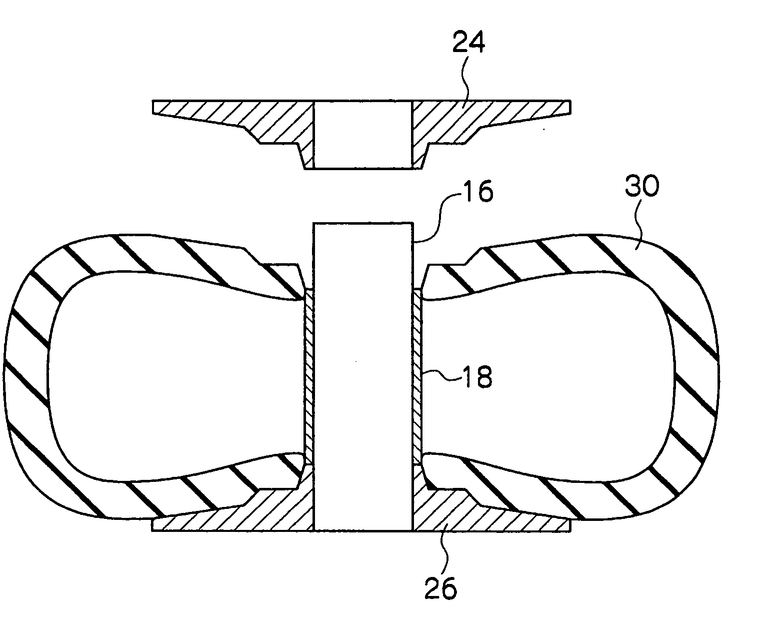
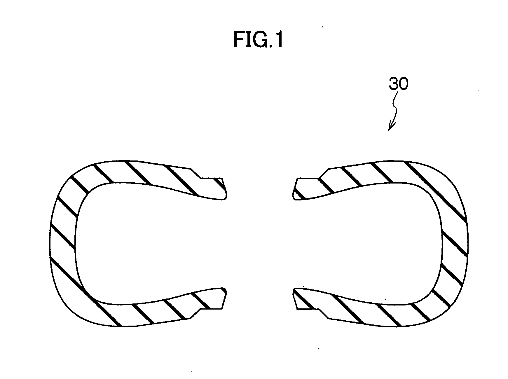
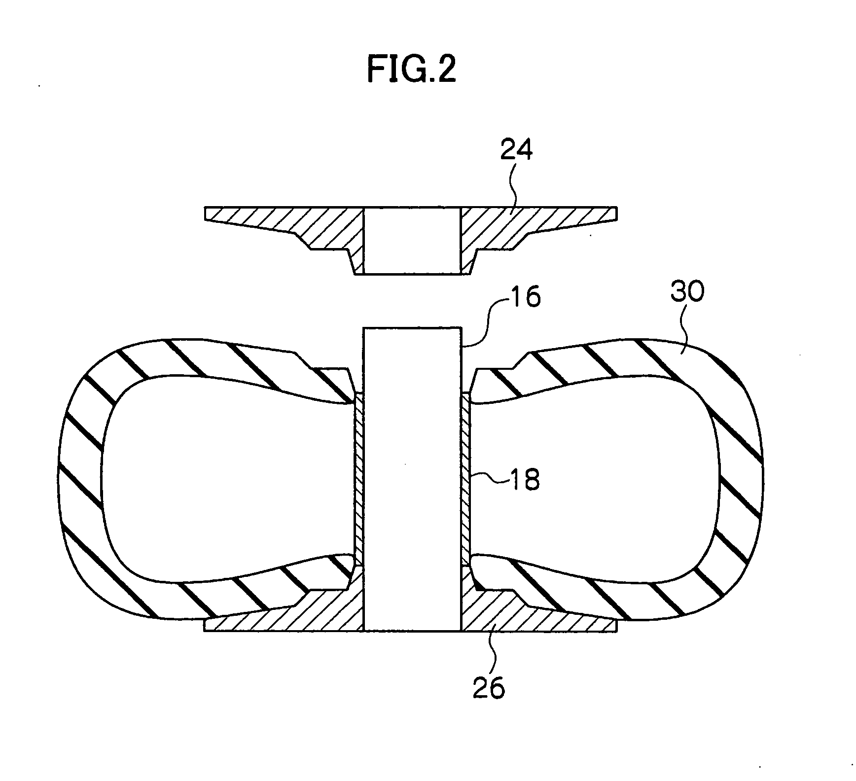
[0017] In this state, the outside edge in a radial direction of the die (die-radial outside edge) of the central lower die part is located at an outside in a die radial (tire-radial) direction of a location which corresponds to half the tire section height of the molding dies. Thereby, when carrying out the above-stated carriage, even if the weight of the green tire is heavy, deformation of the green tire under its own weight, such as drooping, can be prevented.
[0021] Incidentally, with the tire holding unit according to claim 1, the die-radial outside edge of the central lower die part is located tire-radially outside of the location which corresponds to half the tire section height for the molding dies, and thus during carriage, the deformation of the green tire under its own weight is prevented. Therefore, even if a green tire of high weight is carried in a state in which the internal pressure of the bladder is lower than normal, the green tire will not be deformed under its own weight. On the other hand, if the internal pressure of the bladder is lower, the diameter of the green tire which is held by the tire holding unit can be made smaller. Therefore, even if a configuration is adopted in which the die part which forms the tread part is integrally formed with the upper and lower dies, and the number of moving directions is limited to two, instead of a configuration in which the die members constituting the molding dies are individually moved in the vertical direction and the horizontal direction, respectively, the internal pressure of the bladder can be reduced, and the green tire can be loaded into the molding dies from above.
[0023] Thereby, the degree of freedom for pattern design is remarkably increased, and the configuration of the molding dies is simplified, resulting in the productivity being improved.
[0025] As described above deformation of the green tire under its own weight during carriage is prevented by the central lower die part. Therefore, even for a high-weight tire, the air filling pressure of the bladder can be reduced to 50 kPa or lower, which is approximately half or less compared to that for a conventional system.
[0027] Because the present invention is configured as described above, the vulcanization molding can be efficiently carried out, and a convenient-to-use tire holding unit with which the deformation of the green tire is prevented, molding dies having the same, and a tire vulcanization method using the same can be realized.

Problems solved by technology

Incidentally, moving the upper die in the vertical direction and the middle die in the horizontal direction in this way has presented the problems that the apparatus configuration is rendered complicated; pattern design is restricted; and, further, improvement in productivity is hindered.
In addition, there has arisen another problem that, when the green tire is carried to the lower die and placed thereon, the green tire tends to be deformed under its own weight.
However, the weight of a high-weight tire is heavy, and thus lowering the air filling pressure for the bladder causes a deformation of the green tire mainly due to drooping, which makes it impossible to carry out uniform vulcanization.
Therefore, for a high-weight tire, the air filling pressure for the bladder cannot be lowered.

Method used


Image

  • Tire Holding Unit, Molding Dies Having the Same, and Tire Vulcanization Method Using the Same
  • Tire Holding Unit, Molding Dies Having the Same, and Tire Vulcanization Method Using the Same
  • Tire Holding Unit, Molding Dies Having the Same, and Tire Vulcanization Method Using the Same

Examples


Embodiment Construction

[0033] Hereinbelow, an embodiment of the present invention will be described. As shown in FIG. 4, molding dies 12 pertaining to one embodiment of the present invention are dies for ultra-large ORR tires, including a tire holding unit 14 which is freely mountable to and dismountable from the dies.

[0034] The tire holding unit 14 includes a center post 16 which is freely mountable to and dismountable from the molding dies 12, and a bladder 18 which is mounted to the center post 16. In addition, the tire holding unit 14 includes a central upper die part 24 and a central lower die part 26 which constitute the molding dies 12 for tire vulcanization molding, respectively mounted to the center post 16 at either end side of the bladder. Both of the central upper die part 24 and the central lower die part 26 are freely mountable to and dismountable from the center post 16.

[0035] Both of the die-radial outside edges 24E, 26E of the central lower die part 26 and the central upper die part 24 ...


PUM

PropertyMeasurementUnit
air filling pressureaaaaaaaaaa
internal pressureaaaaaaaaaa
heightaaaaaaaaaa

Abstract

The purpose is to provide a convenient-to-use tire holding unit which allows vulcanization molding to be efficiently carried out, and prevents a green tire from being deformed, molding dies having the same, and a tire vulcanization method using the same. Molding dies 12 have a tire holding unit 14 for holding a green tire 30; a lower die main body 28; and an upper die main body 22. The tire holding unit 14 includes a center post 16 which is freely mountable to and dismountable from the molding dies 12; a bladder 18 mounted to the center post 16; and a central upper die part 24 and a central lower die part 26 mounted to the center post 16 at either end side of the bladder, respectively. The central upper die part 24 is freely mountable to and dismountable from the center post 16. In addition, the die-radial outside edge 26E of the central lower die part 26 is located at an outer side in a die radial direction of a location which corresponds to half the tire section height H of the molding dies 12. The upper die main body 22 and the central upper die part 24 constitute an upper die 21, and the lower die main body 28 and the central lower die part 26 constitute a lower die 29.

Description

TECHNICAL FIELD [0001] The present invention relates to a tire holding unit for holding an unvulcanized tire, molding dies having the same, and a tire vulcanization method using the same, and more particularly, relates to a tire holding unit which is most suitable especially for a high-weight tire, molding dies having the same, and a tire vulcanization method using the same. BACKGROUND ART [0002] For vulcanization molding of a pneumatic tire for use with passenger cars, molding dies of a type that are moved only in one direction to be opened and closed are generally used such that a green tire held by an inflated bladder is carried and placed in the lower die. However, in manufacturing a high-weight tire (a high-mass tire), such as a truck vehicle tire or a construction vehicle tire, if this type of molding die is used, a deformation of the green tire due to its own weight, such as drooping, is caused at the time of carriage, which makes it impossible to satisfactorily accommodate t...

Claims


Application Information

Patent Timeline
Patent Type & Authority Applications(United States)
IPC IPC(8): B29D30/28
CPCB29D30/0662B29D30/0016
Inventor SUGIYAMA, TAKESHI
Owner BRIDGESTONE CORP
Learn More