System and method for generating a drive signal

a drive signal and signal generation technology, applied in the direction of positive displacement liquid engine, dynamo-electric converter control, instruments, etc., can solve the problems of limited soft drink variety low product variety/customization of beverage dispensing machines, and plumbed and therefore non-configurabl

Active Publication Date: 2008-03-06
DEKA PROD LLP
View PDF49 Cites 66 Cited by
  • Summary
  • Abstract
  • Description
  • Claims
  • Application Information

AI Technical Summary

Problems solved by technology

Unfortunately, the variety of soft drinks offered by a particular beverage dispensing machine may be limited by the internal plumbing in the machine, which is often hard-plumbed and therefore non-configurable.
Unfortunately, such beverage dispensing machines offer little in terms of product variety / customization.
Additionally as the internal plumbing on such beverage dispensing machines is often hard-plumbed and the internal electronics are often hardwired, the ability of such beverage dispensing machines to offer a high level of variety / customization concerning beverage choices is often compromised.

Method used


Image

  • System and method for generating a drive signal
  • System and method for generating a drive signal
  • System and method for generating a drive signal

Examples


Embodiment Construction

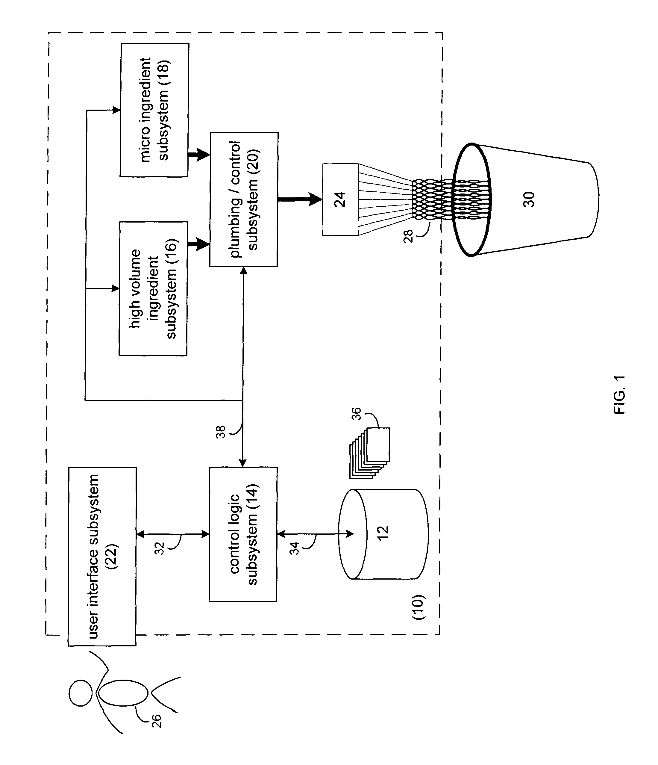
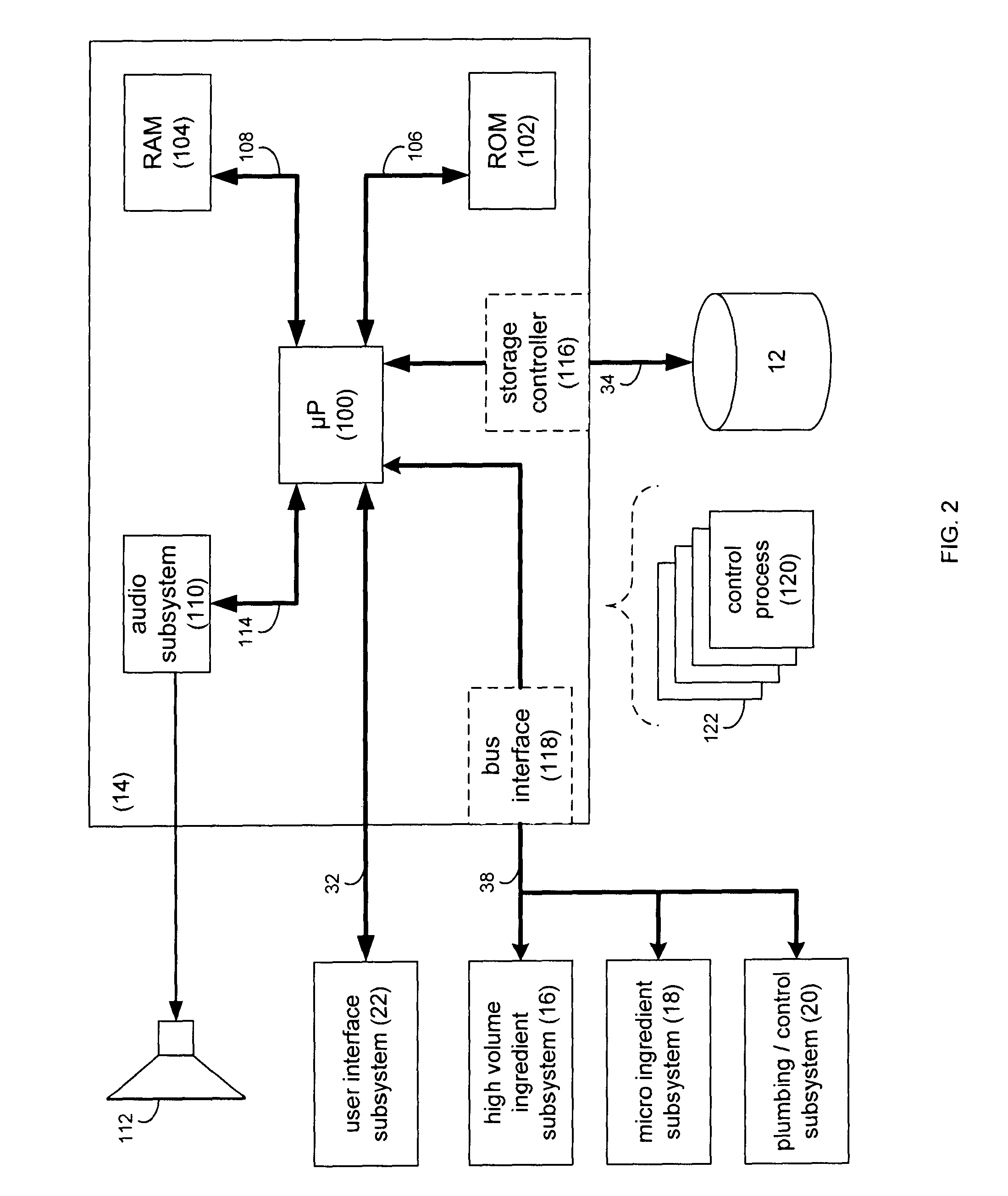
[0025] Referring to FIG. 1, there is shown a generalized-view of beverage dispensing system 10 that is shown to include a plurality of subsystems namely: storage subsystem 12, control logic subsystem 14, high volume ingredient subsystem 16, micro-ingredient subsystem 18, plumbing / control subsystem 20, user interface subsystem 22, and nozzle 24. Each of the above describes subsystems 12, 14, 16, 18, 20, 22 will be described below in greater detail.

[0026] During use of beverage dispensing system 10, user 26 may select a particular beverage 28 for dispensing (into container 30) using user interface subsystem 22. Via user interface subsystem 22, user 26 may select one or more options for inclusion within such beverage. For example, options may include but are not limited to the addition of one or more flavorings (e.g. lemon flavoring, lime flavoring, chocolate flavoring, and vanilla flavoring) into a beverage; the addition of one or more nutraceuticals (e.g. Vitamin A, Vitamin C, Vitam...


PUM


Abstract

A method and computer program product for defining a PWM drive signal having a defined voltage potential. The PWM drive signal has a plurality of “on” portions and a plurality of “off” portions that define a first duty cycle for regulating, at least in part, a flow rate of a pump assembly. At least a portion of the “on” portions of the PWM drive signal are pulse width modulated to define a second duty cycle for the at least a portion of the “on” portions of the PWM drive signal. The second duty cycle regulates, at least in part, the percentage of the defined voltage potential applied to the pump assembly.

Description

CROSS-REFERENCE TO RELATED APPLICATION [0001] The application is a continuation-in-part of application Ser. No. 11 / 276,548 filed Mar. 6, 2006, which is herein incorporated by reference in its entirety.TECHNICAL FIELD [0002] This disclosure relates to dispensing machines and, more particularly, to food product dispensing machines. BACKGROUND [0003] Beverage dispensing machines typically combine one or more concentrated syrups (e.g. cola flavoring and a sweetener) with water (e.g., carbonated or non-carbonated water) to form a soft drink. Unfortunately, the variety of soft drinks offered by a particular beverage dispensing machine may be limited by the internal plumbing in the machine, which is often hard-plumbed and therefore non-configurable. [0004] Accordingly, a typical beverage dispensing machine may include a container of concentrated cola syrup, a container of concentrated lemon-lime syrup, a container of concentrated root beer syrup, a water inlet (i.e. for attaching to a muni...

Claims


Application Information

Patent Timeline
Patent Type & Authority Applications(United States)
IPC IPC(8): H02P8/00H02P27/04B67D7/08
CPCF04B13/02F04B49/065B67D1/0888B67D1/0034F04B51/00B67D1/10G05B15/02B67D1/0036B67D1/104B67D1/122B67D2001/0097F04D15/0027
Inventor BEAVIS, RUSSELL HERBERTDATTOLO, JAMES JASON
Owner DEKA PROD LLP
Why Eureka
Try Eureka