Measurement device, method, program, and recording medium

a measurement device and measurement method technology, applied in measurement devices, digital circuit testing, instruments, etc., can solve problems such as the increase of the influence of the distortion and noise of the spectrum analyze the decrease of the influence of the noise of the spectrum analyzer on the measured result, and the distortion and noise of the spectrum analyzer

Inactive Publication Date: 2008-03-06
ADVANTEST CORP
View PDF3 Cites 20 Cited by
  • Summary
  • Abstract
  • Description
  • Claims
  • Application Information

AI Technical Summary

Benefits of technology

[0020]Another aspect of the present invention is a computer-readable medium having a program of instructions for execution by the computer to perform a process of a measuring device having: a level adjusting unit that receives an output signal output from a device under test, adjusts a level of the output signal, and outputs the resulting output signal; and

Problems solved by technology

However, according to the above conventional technology, an error is generated by a distortion and a noise of the spectrum analyzer in the measured result of the ACLR of the amplifier.
On this occasion, as the level of the output signal of the amplifier supplied to the spectrum analyzer increases, influence of the distortion of the spectrum analyzer exerted on the measured result increases.
On the other hand, as the level of the output signal of

Method used


Image

  • Measurement device, method, program, and recording medium
  • Measurement device, method, program, and recording medium
  • Measurement device, method, program, and recording medium

Examples


first embodiment

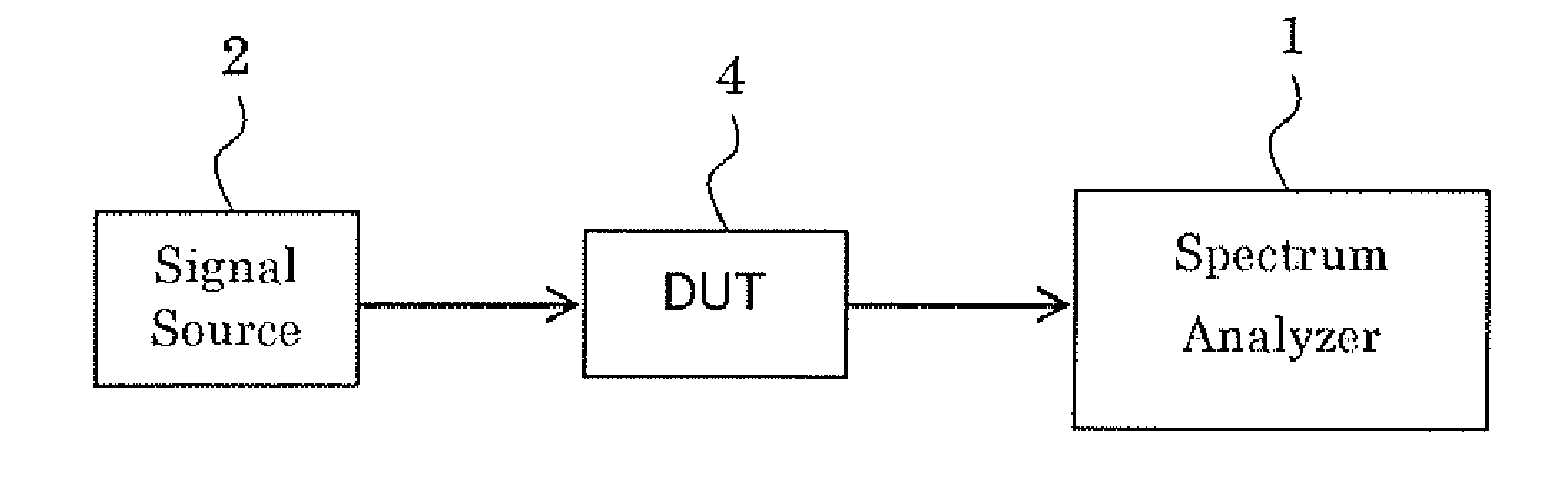
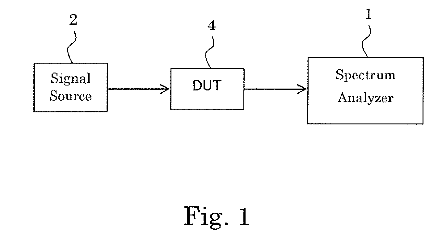
[0034]FIG. 1 is a block diagram showing a configuration of a measurement system in which a spectrum analyzer (measuring device) 1 according a first embodiment of the present invention is utilized. The measuring system includes the spectrum analyzer 1, a signal source 2, and a device under test (DUT) 4.

[0035]The signal source 2 outputs a modulated signal (one-carrier signal or multi-carrier signal used for the WCDMA, for example).

[0036]The device under test (DUT) 4 is an amplifier, for example. The DUT 4 receives the modulated signal from the signal source 2, amplifies the modulated signal, and outputs an output signal.

[0037]The spectrum analyzer 1 receives the output signal from the DUT 4, and measures a characteristic (such as the ACLR: Adjacent Channel Leakage Power Ratio) of the DUT 4.

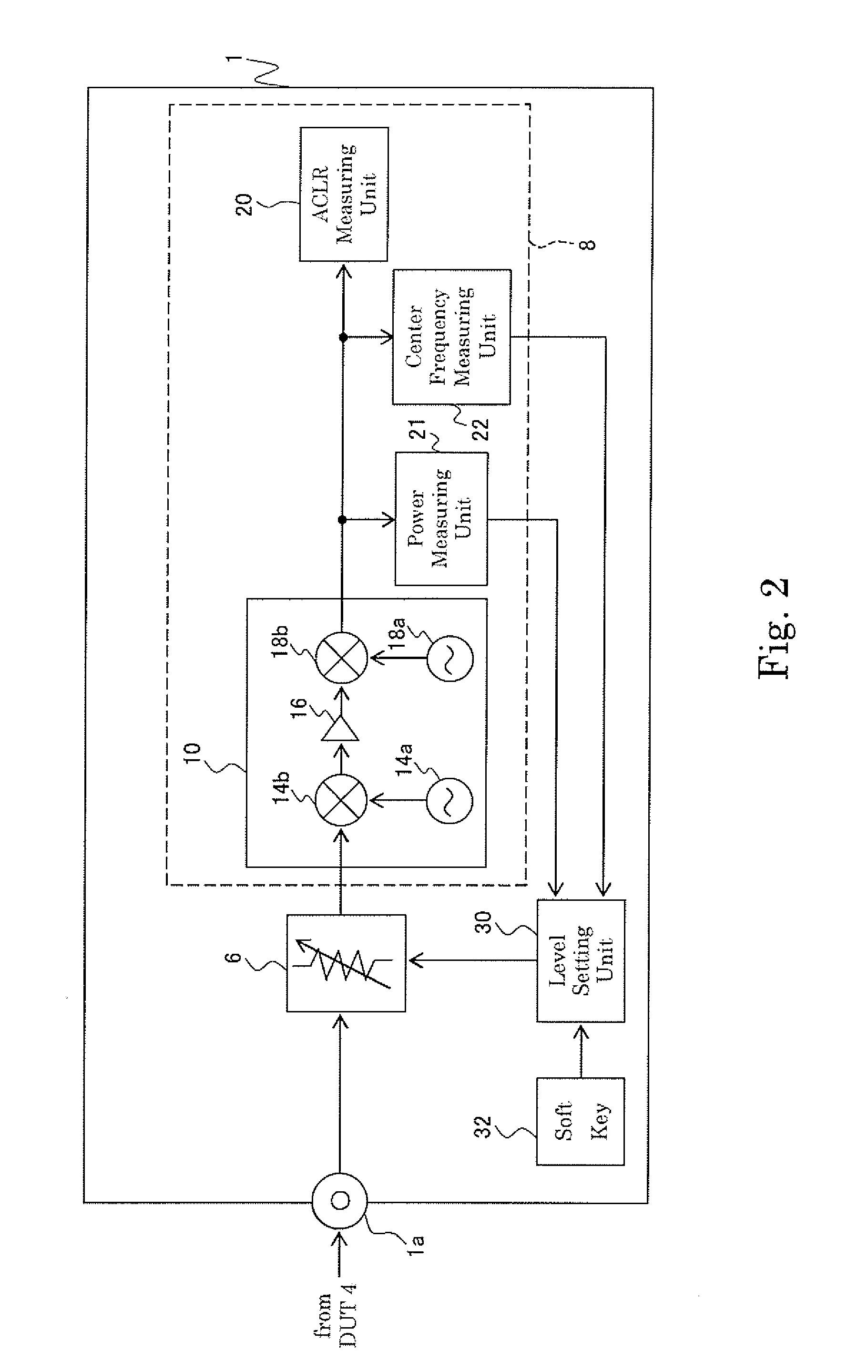
[0038]FIG. 2 is a block diagram showing a configuration of the spectrum analyzer (measuring device) 1 according to the first embodiment. The spectrum analyzer 1 includes a terminal la, an attenuator...

second embodiment

[0092]A second embodiment is different from the first embodiment in that the characteristic of the DUT 4 measured by the spectrum analyzer 1 is the EVM (Error Vector Magnitude)

[0093]FIG. 10 is a block diagram showing a configuration of the spectrum analyzer (measuring device) 1 according to the second embodiment. The spectrum analyzer 1 includes the terminal 1a, the attenuator (level adjusting means) 6, the characteristic measuring unit 8, the level setting unit 30, and the soft key 32. In the following section, similar components are denoted by the same numerals as of the first embodiment, and swill be explained in no more details.

[0094]The terminal 1a, the attenuator (level adjusting means) 6, and the soft key 32 are the same as those of the first embodiment, and a detailed description thereof, therefore, is omitted

[0095]The characteristic measuring unit 8 measures the characteristic, the EVM (Error Vector Magnitude), of the DUT 4 based on the output signal output from the DUT 4.

[...


PUM


Abstract

The level of an output signal output from a device under test is easily adjusted in order to restrain an adverse effect on a result of measuring characteristics of the device under test. A measuring device includes a characteristic measuring unit for measuring characteristics of a device under test based on the output signal output from the device under test, an attenuator for receiving the output signal and adjusting the level of the output signal before supplying it to the characteristic measuring unit, and a level setting unit for setting the degree of the level adjustment of the output signal by the attenuator so as to minimize a measurement error which is caused by the characteristic measurement unit, and changes according to the level of the output signal supplied to the characteristic measuring unit.

Description

TECHNICAL FIELD[0001]The present invention relates to a technology used to measure characteristics (such as ACLR: Adjacent Channel Leakage Power Ratio) of an output signal output from a device under test (DUT).BACKGROUND ART[0002]There has conventionally been practiced a measurement of the ACLR (Adjacent Channel Leakage Power Ratio) of an amplifier which is a DUT (Device Under test) (Refer to a patent document 1 (Japanese Laid-Open Patent Publication (Kokai) No. 2002-319908 (ABSTRACT))).[0003]A signal source supplies an amplifier which is a DUT with a modulated signal. The amplifier amplifies the supplied modulated signal, and outputs the amplified modulated signal. Then, the output signal output from the amplifier is measured by a spectrum analyzer to measure the ACLR of the amplifier.[0004]However, according to the above conventional technology, an error is generated by a distortion and a noise of the spectrum analyzer in the measured result of the ACLR of the amplifier. On this o...

Claims


Application Information

Patent Timeline
IPC IPC(8): G01R23/165G01R15/08G01R19/00G01R23/173G01R31/319
CPCG01R15/08G01R31/31924G01R31/31908G01R23/00
Inventor MIYAUCHI, KOUJIMARUYAMA, YOSHIHIDE
Owner ADVANTEST CORP
Why Eureka
Try Eureka