
Liquid jet head

a liquid jet and recording head technology, applied in printing and other directions, can solve the problems of adverse effects on the performance and image quality of the recording head in ink jetting, the inability to meet the needs of liquid jetting head, etc., to achieve stable liquid jetting performance and high image quality, without increasing the manufacturing cost of the chip driving power source, and without increasing the cost of the ink jet recording head chip cost

Inactive Publication Date: 2008-03-06
CANON KK
View PDF19 Cites 24 Cited by
  • Summary
  • Abstract
  • Description
  • Claims
  • Application Information

AI Technical Summary

Benefits of technology

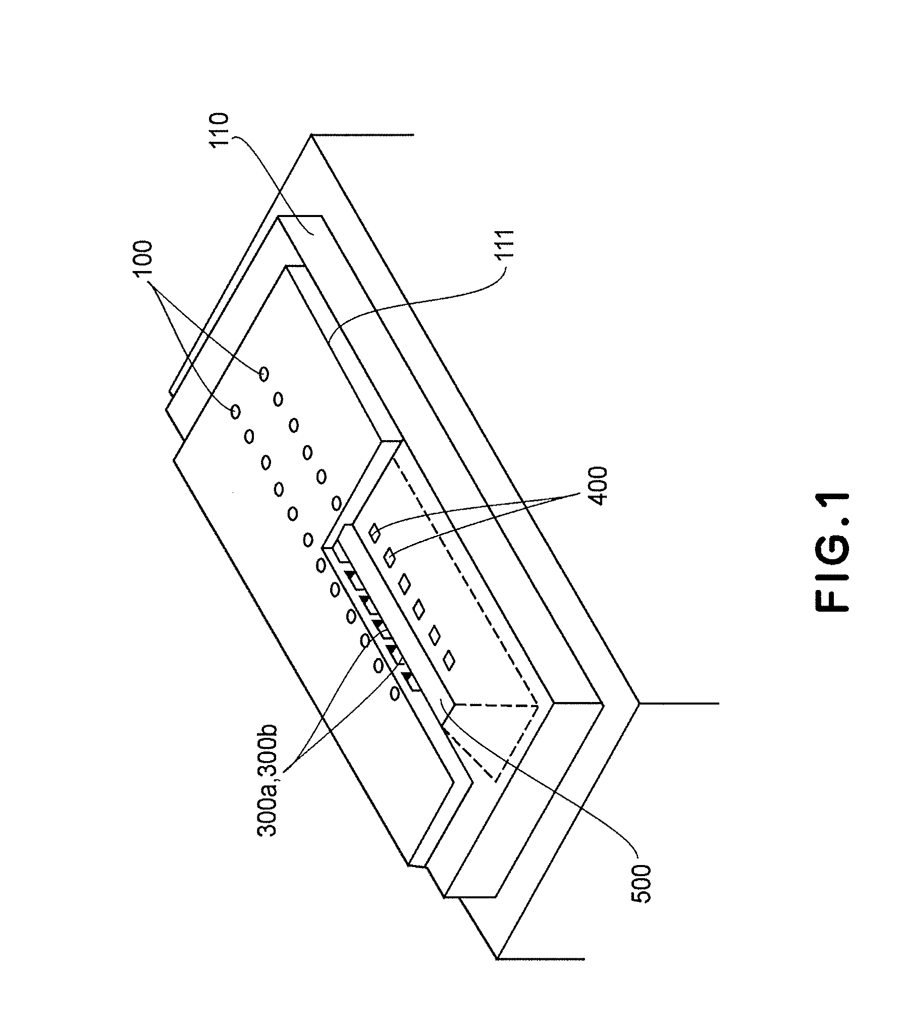
[0017] Thus, the primary object of the present invention is to provide a liquid jetting head in which its nozzles are arranged with a significantly higher pitch than in an ink jet recording head in accordance with the prior art, and which therefore is significantly higher in image quality than a liquid jetting head in accordance with the prior art, without increasing the cost of the ink jet recording head chip, without increasing the manufacturing cost for the chip driving power source, without exacerbating the poor bubble generation efficiency attributable to long pulses, and also, without making a liquid jetting head chip unstable in liquid jetting performance. Another object of the present invention is to provide a liquid jetting head, the liquid jetting nozzles of which are significantly small in liquid droplet size than any of liquid jetting heads in accordance with the prior art.
[0019] According to the present invention, it is possible to achieve a high level of image quality without increasing ink jet recording head chip cost, without increasing the manufacturing cost for the chip driving power source, without exacerbating the poor bubble generation efficiency attributable to long pulses, and also, without making a liquid jetting head chip unstable in liquid jetting performance.

Problems solved by technology

On the other hand, it has its own problems.
For example, the heat which the electro-thermal transducers generate accumulates in the recording head, changing thereby the recording head in the volume (size) of an ink droplet the recording head ejects, or the electro-thermal transducers are adversely affected by the cavitation attributable to the collapsing of bubbles.
Further, in the case of a recording head which employs the abovementioned ink jetting method, the air having dissolved into ink forms air bubbles in the recording head, and these air bubbles adversely affect the recording head in ink jetting performance and image quality.
However, this structural arrangement requires two ink containers per color, that is, one ink container for the ink lighter in color, and the other for the ink darker in color, adding thereby to apparatus cost.
This solution also suffers from a problem.
This method also results in the reduction in printing speed, because the increase in the number of times a recording head is moved across recording medium per scanning increases the length of time it takes to complete a portion of an image, which corresponds to each scanning line.
However, this method also has its limitation.
That is, it has been well-known that reducing an ink jet recording head in ink droplet size reduces the ink jet head in printing efficiency, and also, that increasing an ink jet recording head in resolution by reducing it in ink droplet size (ink jetting orifice size) makes its heaters disproportionally large for the number of its ink jetting orifices per unit area, making it thereby difficult to thread (route) heater wiring.
Thus, an attempt to increases an ink jet recording head in resolution beyond a certain value makes it impossible to arrange the heaters of the recording head in a straight line.
This problem is not limited to the heater arrangement; the passages through which ink is supplied suffer from the same problem.
However, this structural arrangement also has problems.
Therefore, even if the heater 4000 of each short nozzle is made rectangular to allow the ink passage 3000 of the adjacent long nozzle to be wider, the problem that the refill frequency is not high enough for satisfactory image formation cannot be completely eliminated.
Further, it has been known that the abovementioned air bubbles are likely to collect in this dead zone, and also, the collection of air bubbles in a nozzle makes the nozzle unstable in ink jetting performance, making therefore an ink jet recording head unstable in ink jetting performance.
The third problem is the increase in the manufacturing cost of an ink jet recording head chip, which results from the increase in size of the portion of the recording head having multiple nozzles.
Therefore, the greater the chip size, the smaller the number of ink jet recording head chips obtainable from a single wafer, and therefore, the higher the manufacturing cost of each ink jet recording head chip.
Therefore, the substrate of the nozzle plate structured as shown in FIG. 12 has to be greater in size, being therefore greater in manufacturing cost.
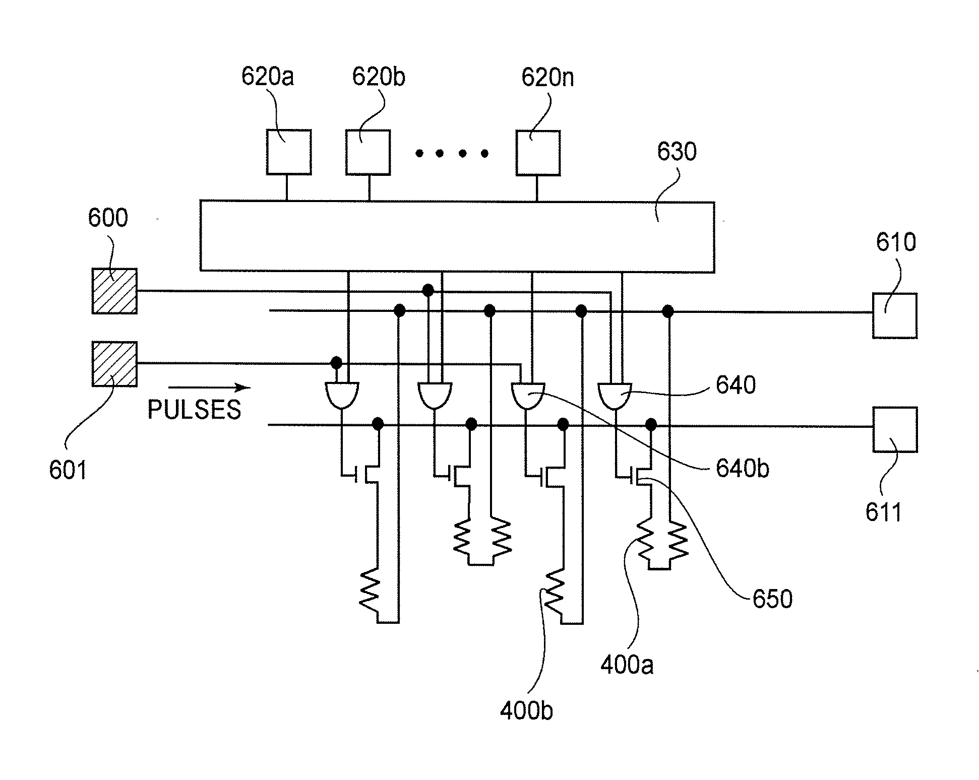
Thus, if they are the same in the length of time electric current flows through them (same in driving pulse width), an image forming apparatus must be provided with two power sources for driving the heaters, which are different in power (voltage), or a circuit for making the voltage applied to the former different in magnitude from the voltage applied to the latter, increasing thereby the cost of manufacturing the power source.
However, this method was also problematic in that it sometimes prevented heater driving pulses from reaching the heaters within the length of time tolerable based on printing speed, and also, created the problem that not only was the heater which received long pulses inferior in bubble generation efficiency to the heater which received short pulses, but also, was different in the pattern of heat flux from the heater which received short pulses, making the ink jet recording head unstable in ink jetting performance.
It has been known that the smaller the liquid droplet (ink droplet) in volume (roughly several pico-liters), the more conspicuous the problem (ink jet recording head is unstable in ink jetting performance).

Method used


Image

  • Liquid jet head
  • Liquid jet head
  • Liquid jet head

Examples


embodiment 1

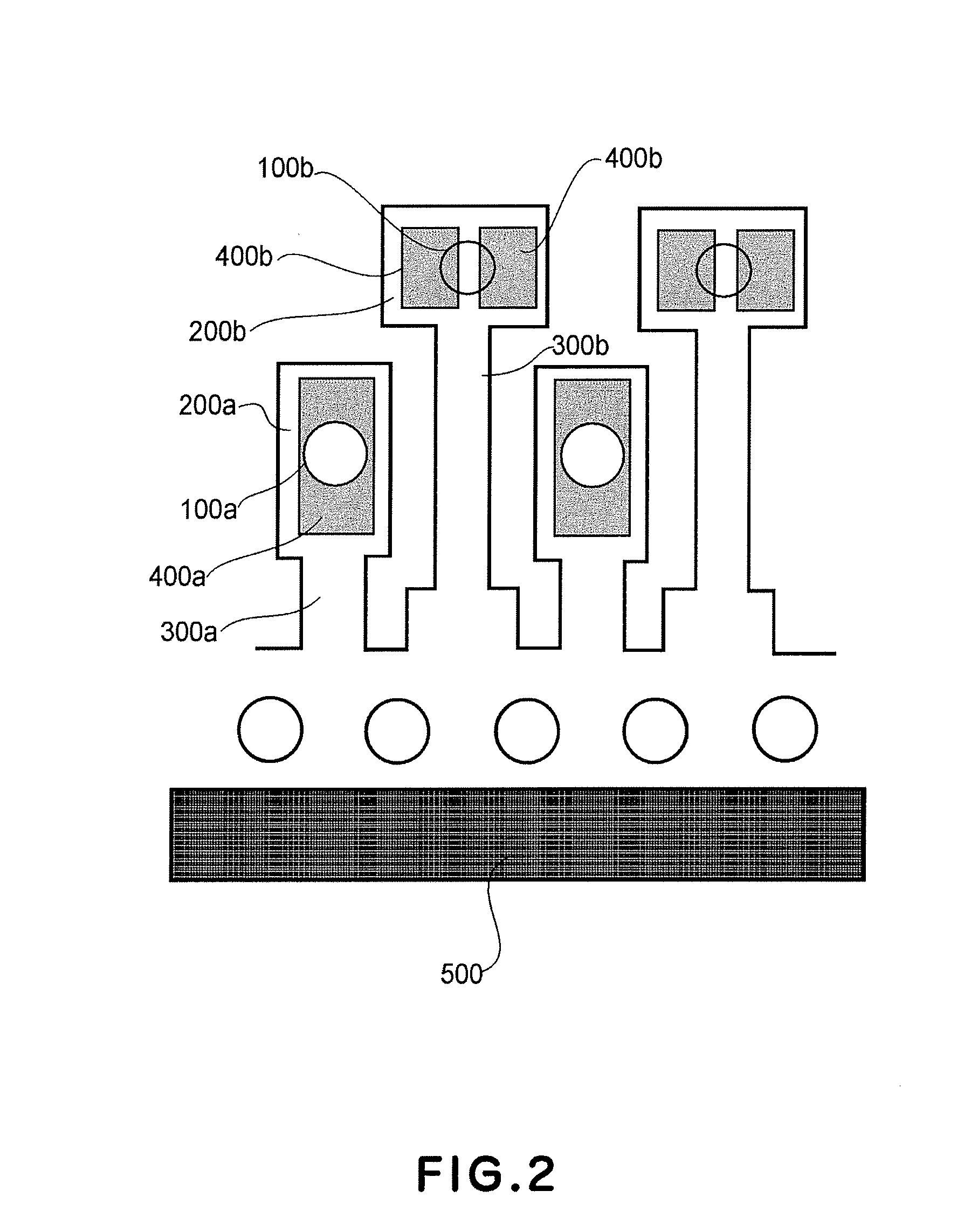
[0040]FIG. 2 shows the nozzle structure of the ink jet recording head in the first preferred embodiment of the present invention. In the following description of this embodiment, the structure of the ink jet recording head is described with reference to the portion of the ink jet recording head on one side of the common ink delivery channel 500. This, however, is not intended to limit the present invention in scope. That is, the other side of the common ink delivery channel 500 may also be provided with sets of nozzles similar to the groups of nozzles which will be described next. One end of a first liquid passage 300a and one end of a second liquid passage 300b are in connection with a pressure chamber 200a and a pressure chamber 200b, respectively, whereas the other end of the first liquid passage 300a and the other end of the second liquid passage 300b are in connection to the common ink delivery channel 500. Referring to FIG. 2, the ink jet recording head in this embodiment has ...

embodiment 2

[0058]FIG. 3 is a plan view of a portion of the ink jet recording head chip in the second embodiment of the present invention, showing its nozzle structure. This embodiment is similar to the first embodiment in that one end of each ink passage 300a is connected to the corresponding pressure chamber 200a, whereas the other end is connected to the common ink delivery channel 500, and also, in that one end of each ink passage 300b is connected to the corresponding pressure chamber 200b, whereas the other end is connected to the common ink delivery channel 500. Referring to FIG. 3, the ink jet recording head in this embodiment has multiple first ink jetting orifices 100a, which are relatively small in the distance from the common ink delivery channel 500, and multiple second ink jetting orifices 100b, which are relatively large in the distance from the common ink delivery channel 500. The first orifices 100a are aligned in a single straight row parallel to the lengthwise direction of th...

embodiment 3

[0069]FIG. 4 is a plan view of the ink jet recording head in the third embodiment of the present invention, showing its nozzle structure. One end of each ink passage 300a is connected to the corresponding pressure chamber 200a, whereas the other end is connected to the common ink delivery channel 500. Also, one end of each ink passage 300b is connected to the corresponding pressure chamber 200b, whereas the other end is connected to the common ink delivery channel 500. Referring to FIG. 4, the ink jet recording head chip in this embodiment has multiple first ink jetting orifices 100a, which are relatively small in the distance from the common ink delivery channel 500, and multiple second ink jetting orifices 100b, which are relatively large in the distance from the common ink delivery channel 500. The first orifices 100a are aligned in a single straight row parallel to the lengthwise direction of the common ink delivery channel 500, and the second orifices 100b are also aligned in a...


PUM


Abstract

A liquid ejecting head includes a plurality of ejection outlets for ejecting droplets; liquid flow paths in fluid communication with said ejection outlets; and a liquid supply opening for supplying the liquid to said liquid flow path; wherein said ejection outlets include first ejection outlets and second ejection outlets which are disposed at least at one side of said liquid supply opening, wherein said first ejection outlets are nearer from said liquid supply opening than said second ejection outlets, and said first ejection outlets and said second ejection outlets are arranged in a staggered fashion; first recording elements for said first ejection outlets; second recording elements for said second ejection outlets, wherein each of said first recording elements includes one heat generating resistor in the form of a rectangular shape having a long side extending along a direction crossing with an arranging direction of said ejection outlets; and wherein said second recording element includes a plurality of heat generating resistors each of which is in the form of a rectangular shape and which are adjacent to each other at the long sides thereof, said plurality of heat generating resistors being electrically connected in series.

Description

FIELD OF THE INVENTION AND RELATED ART [0001] The present invention relates to a liquid jetting head for recording on recording medium by jetting ink onto the recording medium. [0002] In recent years, various recording apparatuses have come to be widely used, and at the same time, demand has been increasing for image forming apparatuses which are significantly higher in recording speed, resolution, and image quality, but, are significantly lower in noise than any of the recording apparatuses in accordance with the prior art. As one of the recording apparatuses which can meet these demands, an ink jet recording apparatus may be listed. [0003] Among various methods for jetting ink, an ink jetting method which employs an electro-thermal transducer as an energy generating element enjoys various advantageous over the other types of ink jetting method. For example, it does not require a large space for the energy generating elements and is simple in structure. Further, it allows a large n...

Claims


Application Information

Patent Timeline
IPC IPC(8): B41J2/05
CPCB41J2002/14475B41J2/145B41J2/1404B41J2002/14177B41J2002/14403B41J2/14112B41J2/1408
Inventor OIKAWA, MASAKIKANEKO, MINEOTSUCHII, KENYAMANE, TORUTOMIZAWA, KEIJIMATSUMOTO, MITSUHIROIDE, SHUICHITAKINO, KANSUINABESHIMA, NAOZUMI
Owner CANON KK
Learn More