Power transmission system and power receiving jacket
a transmission system and power technology, applied in the field of power transmission, can solve the problems of difficult layout design, difficult to enhance the transmission efficiency of electric power, and difficult to minimize the power transmitting unit and the power receiving unit, so as to reduce manufacturing costs, improve the transmission efficiency of electric power, and effectively transmit electric power
- Summary
- Abstract
- Description
- Claims
- Application Information
AI Technical Summary
Benefits of technology
Problems solved by technology
Method used
Image
Examples
embodiment 1
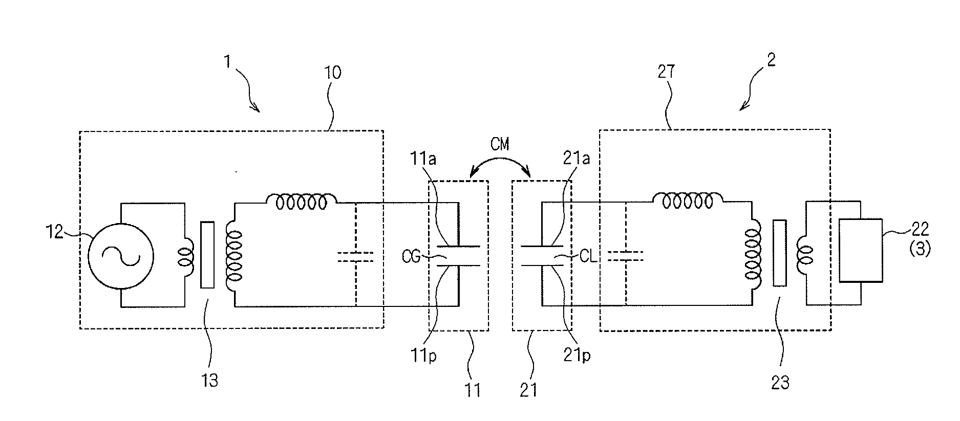
[0041]FIG. 4 is a functional block diagram schematically illustrating the configuration of the power transmission system according to the present invention. As illustrated in FIG. 4, the alternating-current voltage supplied from the voltage generation circuit 12 in the power transmitting device 1 is amplified by an amplifier 102, stepped up by the step-up transformer 13, and supplied to the coupling electrode 11. The voltage generation circuit 12, the amplifier 102, the step-up transformer 13, and the coupling electrode 11 are embedded in a power transmitting stand described later. The alternating-current voltage transmitted from the coupling electrode 11 in the power transmitting device 1 to the coupling electrode 21 in the power receiving jacket 2 is stepped down by the step-down transformer 23, and supplied to a load circuit 22 after having been rectified by a rectifier 203.
[0042]FIG. 5 is a schematic view illustrating the configuration of the power transmission system according ...
embodiment 2
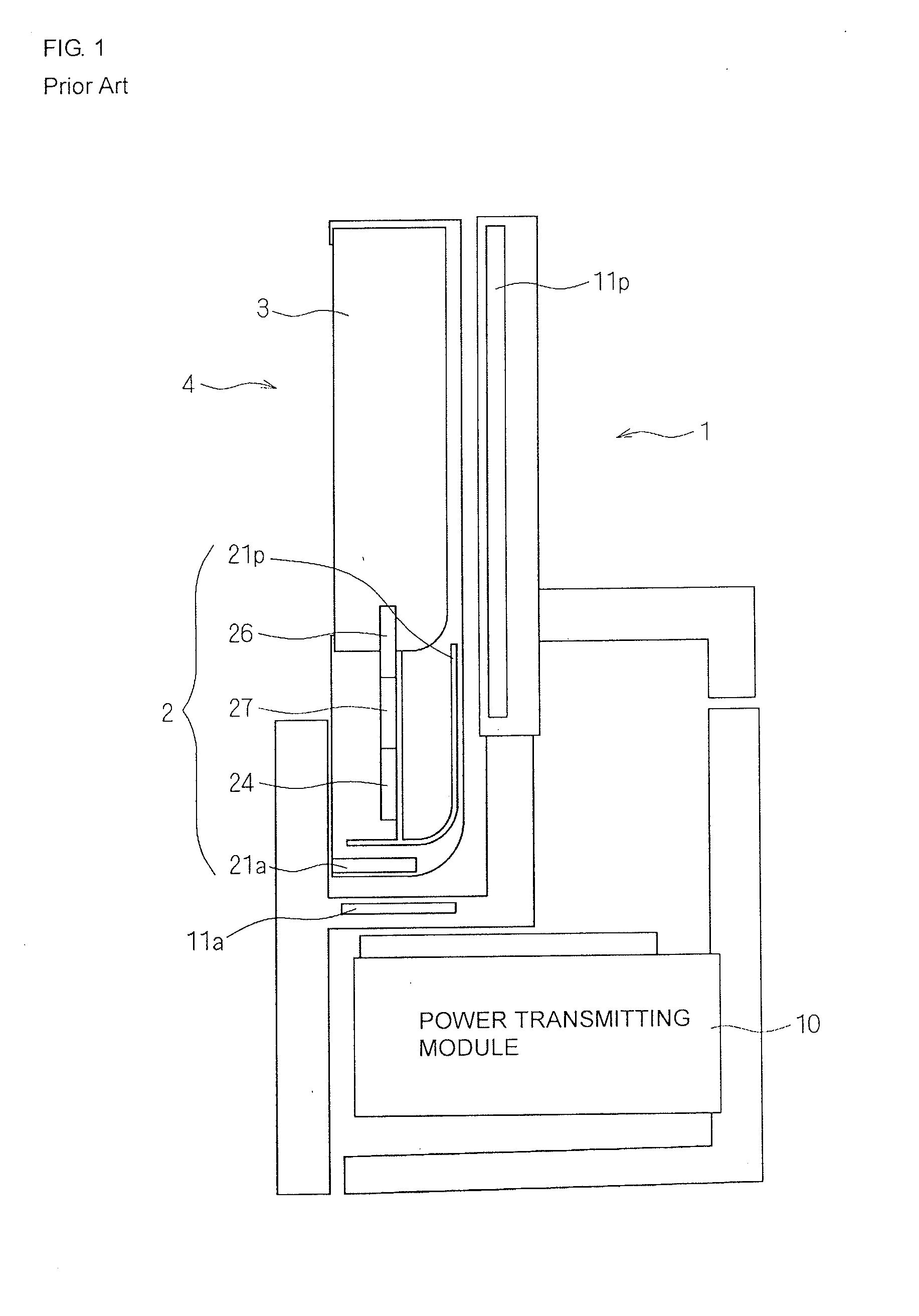
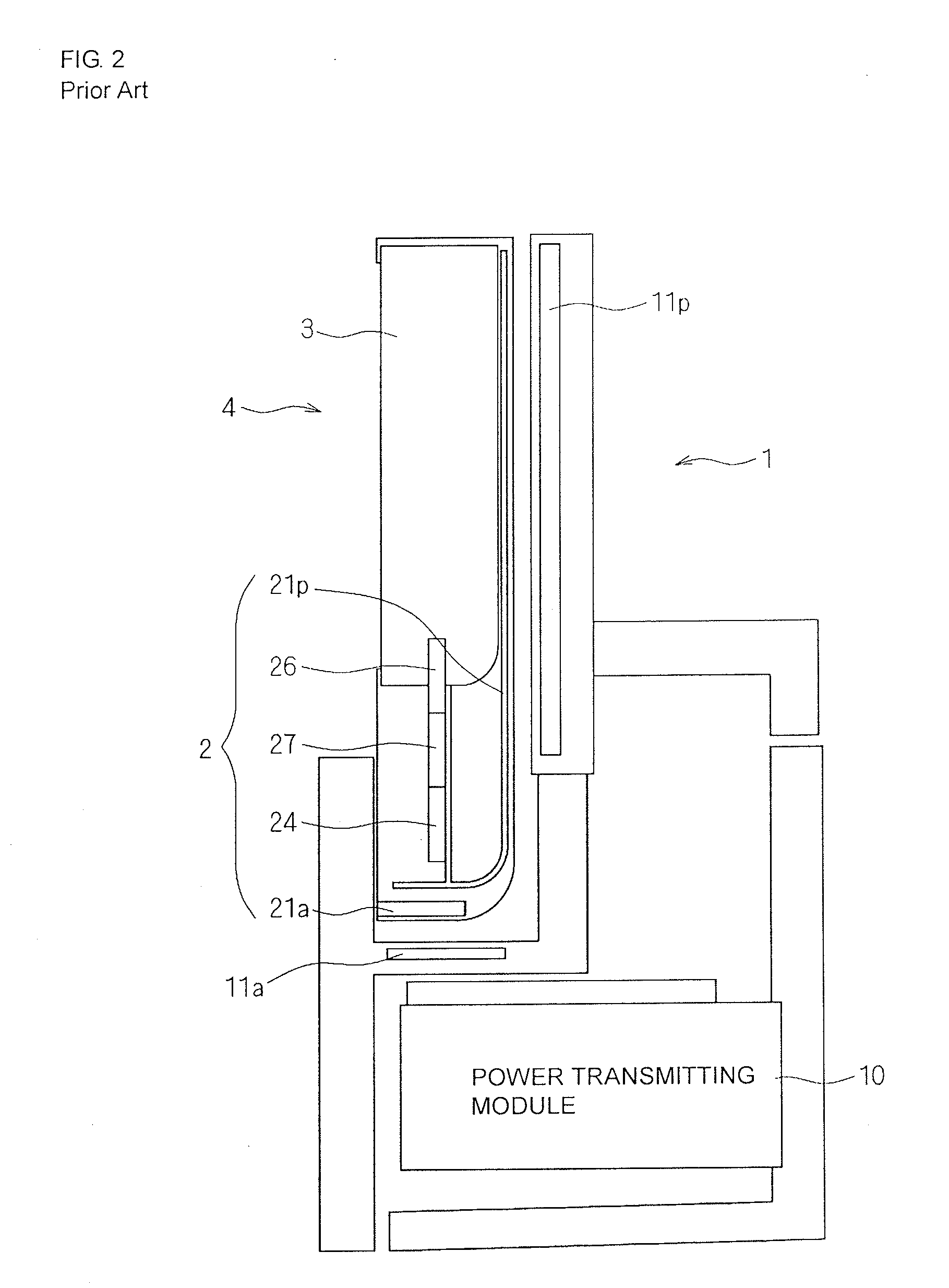
[0053]FIG. 8 is a schematic view illustrating the configuration of a power transmission system according to the present invention. In FIG. 8, in the power transmitting stand (power transmitting unit) 1 including the power transmitting module 10, both of the passive electrodes 11p and the active electrode 11a are provided in a surface to which the power receiving jacket 2 is attached and which supports the power receiving jacket 2. The active electrode 11a is disposed nearly in the middle of the surface of the power transmitting stand 1 to which the power receiving jacket 2 is attached and which supports the power receiving jacket 2, and the active electrode 11a is disposed so as to be sandwiched between the two passive electrodes 11p. In other words, the active electrode 11a and the power receiving electrodes 11p in the power transmitting stand 1 are provided at a position (the surface) facing the rear face of the power receiving jacket 2 when the power receiving jacket 2 is attache...
embodiment 3
[0064]FIG. 10 is a schematic view illustrating the configuration of a power transmission system according to an embodiment 3 of the present invention. In FIG. 10, in the power transmitting stand (power transmitting unit) 1 including the power transmitting module 10, both of the passive electrodes 11p and the active electrode 11a are provided in a surface to which the power receiving jacket 2 is attached and which supports the power receiving jacket 2. The active electrode 11a is disposed nearly in the middle of the surface of the power transmitting stand 1 to which the power receiving jacket 2 is attached and which supports the power receiving jacket 2, and the active electrode 11a is disposed so as to be sandwiched between the two passive electrodes 11p. In other words, the active electrode 11a and the power receiving electrodes 11p in the power transmitting stand 1 are provided at a position (the surface) facing the rear face of the power receiving jacket 2 when the power receivin...
PUM
 Abstract
Description
Claims
Application Information
 - R&D
- Intellectual Property
- Life Sciences
- Materials
- Tech Scout
- Unparalleled Data Quality
- Higher Quality Content
- 60% Fewer Hallucinations
Browse by: Latest US Patents, China's latest patents, Technical Efficacy Thesaurus, Application Domain, Technology Topic, Popular Technical Reports.
© 2025 PatSnap. All rights reserved.Legal|Privacy policy|Modern Slavery Act Transparency Statement|Sitemap|About US| Contact US: help@patsnap.com


